


In this article, we’ll integrate the M5Stack Dial into Home Assistant (HA) — a multifunctional system with many interesting features to control our setup.
Index
M5Stack Dial
M5Stack is already a well-known brand to us, with creations like the M5Stack CoreS3SE and the classic Atom Echo. Today, we are going to integrate the M5Stack Dial into Home Assistant — a device that includes the following components:

All these features packed into a single, ready-to-use device which make the M5Dial a truly compelling gadget. And since it's powered by an ESP32-S3, we can easily integrate it into Home Assistant using ESPHome.
Mr. Avocado
As usual, we wanted to make the most of these features by building a fun and practical project. This time, it's something special — a device co-designed with our Patreon community.
We named it Mr. Avocado, a playful nod to the iconic “Mr. Potato.” The goal was to create a multifunctional device with the following capabilities:
Prerequisites
To integrate the M5Dial into Home Assistant, you’ll need:
🥑 If you’re just getting started with ESPHome, I highly recommend checking out the academy workshop — it’s a great way to get the most out of it!
Follow these steps to integrate the M5Stack Dial into Home Assistant:
1. In Home Assistant, open the ESPHome add-on, click “New Device”, then “Continue.”
2. Give your device a name (for example, “M5Stack Dial”) and click “Next.”
3. For the device type, select “ESP32-S3.” You’ll see that a new tile has been created for your device.
4. Click “Skip”, then “Edit” on your device’s tile. Copy the default code that appears and save it—you’ll need parts of it later.
5. Now, copy the code below and use it to replace the default code in ESPHome.
substitutions:
# Device customization
# Personalización del dispositivo
name: m5stack-dial
friendly_name: M5Stack Dial
background_color: 'fab02b'
background_image: https://aguacatec.es/wp-content/uploads/2025/02/mravocado_background_white.jpg
background_image_saver: https://aguacatec.es/wp-content/uploads/2025/02/mravocado_bg_off.jpg
background_image_device: https://aguacatec.es/wp-content/uploads/2025/02/mravocado_bg_device.jpeg
# Icons
# Iconos
icon_1: mdi:led-strip-variant
icon_2: mdi:thermostat
icon_3: mdi:robot-vacuum
icon_4: mdi:printer
icon_5: mdi:printer-3d-nozzle
icon_6: mdi:fan
icon_7: mdi:air-humidifier
icon_8: mdi:ceiling-light
# Sounds
# Sonidos
menu_sound: 'beep:d=64,o=5,b=255:c7'
alarm_sound: 'xmen:d=4,o=6,b=200:16f#5,16g5,16b5,16d,c#,8b5,8f#5,p,16f#5,16g5,16b5,16d,c#,8b5,8g5,p,16f#5,16g5,16b5,16d,c#,8b5,8d,2p,8c#,8b5,2p'
# Example of Lights
# Ejemplo de Luces
desk_led: light.tira_led_escritorio
lamp: light.lampara
# Example of Thermostat
# Ejemplo de Termostatos
climate: climate.salon
aircon: climate.aircon
# Example of Vacuum
# Ejemplo de Aspirador
vacuum: vacuum.robot_aspirador
# Example of Switches
# Ejemplo de Enchufes
printer: switch.regleta_l3
printer3d: switch.regleta_l4
# Example of dehumidifier
# Ejemplo de Deshumidificador
dehumidifier: humidifier.deshumidificador
# NFC/RFID Tags
# Etiquetas NFC/RFID
# tag1: C3-DB-4F-28
# tag2: 03-55-E5-13
# Other settings
# Otros ajustes
allowed_characters: " ¿?¡!#%'()+,-./:°0123456789ABCDEFGHIJKLMNOPQRSTUVWYZabcdefghijklmnopqrstuvwxyzáéíóú"
################################################################################################################
esphome:
name: ${name}
friendly_name: ${friendly_name}
on_boot:
then:
- pcf8563.read_time:
- display.page.show: home
platformio_options:
board_build.flash_mode: dio
esp32:
board: esp32-s3-devkitc-1
flash_size: 8MB
framework:
type: esp-idf
wifi:
ssid: !secret wifi_ssid
password: !secret wifi_password
# Enable fallback hotspot (captive portal) in case wifi connection fails
ap:
ssid: "M5Stack-Dial Fallback Hotspot"
password: "Aosad564JQR"
api:
encryption:
key: "QYmasdasdsd71H8/dlyD1BI5cU10X234234fhg="
services:
- service: play_sound
variables:
song: string
volume: int
then:
- lambda: "id(script_rtttl_play).execute(song, volume);"
script:
- id: script_rtttl_play
parameters:
song: string
volume: int
mode: single
then:
- lambda: |-
float volume_f = (volume>0) ? ((float)clamp(volume, 0, 100))/100.0f : 1.0f;
id(buzzer).set_max_power(volume_f);
- rtttl.play:
rtttl: !lambda 'return (song.find('':'') == std::string::npos) ? ("song:d=16,o=5,b=100:" + song).c_str() : song.c_str();'
ota:
- platform: esphome
password: "0935e9dsasdfgdb3d8934c"
logger:
captive_portal:
binary_sensor:
- platform: gpio
name: "Front Button"
id: front_button
pin:
number: GPIO42
inverted: true
internal: true
on_press:
then:
- if:
condition:
switch.is_on: menu_sounds
then:
- rtttl.play: ${menu_sound}
- if:
condition:
light.is_on: backlight
then:
- if:
condition:
display.is_displaying_page: device_control
then:
- if:
condition:
lambda: |-
return id(device) == 1;
then:
- homeassistant.action:
service: light.toggle
data:
entity_id: ${desk_led}
- if:
condition:
lambda: |-
return id(device) == 2;
then:
- homeassistant.action:
service: climate.toggle
data:
entity_id: ${climate}
- if:
condition:
lambda: |-
return id(device) == 3;
then:
- if:
condition:
lambda: 'return id(device_vacuum).state == "cleaning";'
then:
- homeassistant.action:
service: vacuum.pause
data:
entity_id: ${vacuum}
else:
- homeassistant.action:
service: vacuum.start
data:
entity_id: ${vacuum}
- if:
condition:
lambda: |-
return id(device) == 4;
then:
- homeassistant.action:
service: switch.toggle
data:
entity_id: ${printer}
- if:
condition:
lambda: |-
return id(device) == 5;
then:
- homeassistant.action:
service: switch.toggle
data:
entity_id: ${printer3d}
- if:
condition:
lambda: |-
return id(device) == 6;
then:
- homeassistant.action:
service: climate.toggle
data:
entity_id: ${aircon}
- if:
condition:
lambda: |-
return id(device) == 7;
then:
- homeassistant.action:
service: humidifier.toggle
data:
entity_id: ${dehumidifier}
- if:
condition:
lambda: |-
return id(device) == 8;
then:
- homeassistant.action:
service: light.toggle
data:
entity_id: ${lamp}
- if:
condition:
display.is_displaying_page: locked_screen
then:
- switch.turn_on: mravocado_display
- light.turn_on:
id: backlight
brightness: 100%
- display.page.show: home
- if:
condition:
display.is_displaying_page: home
then:
- if:
condition:
lambda: |-
return id(device) > 0;
then:
- light.turn_on:
id: backlight
brightness: 100%
- display.page.show: device_control
else:
- switch.turn_on: mravocado_display
- light.turn_on:
id: backlight
brightness: 100%
- display.page.show: home
- lambda: |-
id(inactivity_time) = 0;
- platform: gpio
name: Hold Button
pin: GPIO46
internal: True
- platform: touchscreen
name: "Home Button"
internal: true
x_min: 0
x_max: 240
y_min: 0
y_max: 80
page_id: device_control
on_press:
- display.page.show: home
- if:
condition:
switch.is_on: menu_sounds
then:
- rtttl.play: ${menu_sound}
- lambda: |-
id(inactivity_time) = 0;
- platform: touchscreen
name: "Device Button"
internal: true
x_min: 81
x_max: 160
y_min: 80
y_max: 240
page_id: device_control
on_press:
- if:
condition:
switch.is_on: menu_sounds
then:
- rtttl.play: ${menu_sound}
- if:
condition:
lambda: |-
return id(device) == 1;
then:
- homeassistant.action:
service: light.toggle
data:
entity_id: ${desk_led}
- if:
condition:
lambda: |-
return id(device) == 2;
then:
- homeassistant.action:
service: climate.toggle
data:
entity_id: ${climate}
- if:
condition:
lambda: |-
return id(device) == 3;
then:
- if:
condition:
lambda: 'return id(device_vacuum).state == "cleaning";'
then:
- homeassistant.action:
service: vacuum.pause
data:
entity_id: ${vacuum}
else:
- homeassistant.action:
service: vacuum.start
data:
entity_id: ${vacuum}
- if:
condition:
lambda: |-
return id(device) == 4;
then:
- homeassistant.action:
service: switch.toggle
data:
entity_id: ${printer}
- if:
condition:
lambda: |-
return id(device) == 5;
then:
- homeassistant.action:
service: switch.toggle
data:
entity_id: ${printer3d}
- if:
condition:
lambda: |-
return id(device) == 6;
then:
- homeassistant.action:
service: climate.toggle
data:
entity_id: ${aircon}
- if:
condition:
lambda: |-
return id(device) == 7;
then:
- homeassistant.action:
service: humidifier.toggle
data:
entity_id: ${dehumidifier}
- if:
condition:
lambda: |-
return id(device) == 8;
then:
- homeassistant.action:
service: light.toggle
data:
entity_id: ${lamp}
- lambda: |-
id(inactivity_time) = 0;
- platform: touchscreen
name: "Minus Button"
internal: true
x_min: 0
x_max: 80
y_min: 80
y_max: 240
page_id: device_control
on_press:
- if:
condition:
switch.is_on: menu_sounds
then:
- rtttl.play: ${menu_sound}
- if:
condition:
display.is_displaying_page: device_control
then:
- if:
condition:
lambda: |-
return id(device) == 1;
then:
- homeassistant.action:
service: light.turn_on
data:
entity_id: ${desk_led}
brightness_step_pct: '-10'
- if:
condition:
lambda: |-
return id(device) == 2;
then:
- homeassistant.action:
service: climate.set_temperature
data:
entity_id: ${climate}
data_template:
temperature: '{{ my_variable | float }}'
variables:
my_variable: |-
return id(thermostat_temperature).state - 1.0;
- if:
condition:
lambda: |-
return id(device) == 6;
then:
- homeassistant.action:
service: climate.set_temperature
data:
entity_id: ${aircon}
data_template:
temperature: '{{ my_variable | float }}'
variables:
my_variable: |-
return id(aircon_temperature).state - 1.0;
- if:
condition:
lambda: |-
return id(device) == 7;
then:
- homeassistant.action:
service: humidifier.set_humidity
data:
entity_id: ${dehumidifier}
data_template:
humidity: '{{ my_variable | float }}'
variables:
my_variable: |-
return id(dehumidifier_humidity).state - 5.0;
- if:
condition:
lambda: |-
return id(device) == 8;
then:
- homeassistant.action:
service: light.turn_on
data:
entity_id: ${lamp}
brightness_step_pct: '-10'
- lambda: |-
id(inactivity_time) = 0;
- platform: touchscreen
name: "Plus Button"
internal: true
x_min: 161
x_max: 240
y_min: 80
y_max: 240
page_id: device_control
on_press:
- if:
condition:
switch.is_on: menu_sounds
then:
- rtttl.play: ${menu_sound}
- if:
condition:
display.is_displaying_page: device_control
then:
- if:
condition:
lambda: |-
return id(device) == 1;
then:
- homeassistant.action:
service: light.turn_on
data:
entity_id: ${desk_led}
brightness_step_pct: '10'
- if:
condition:
lambda: |-
return id(device) == 2;
then:
- homeassistant.action:
service: climate.set_temperature
data:
entity_id: ${climate}
data_template:
temperature: '{{ my_variable | float }}'
variables:
my_variable: |-
return id(thermostat_temperature).state + 1.0;
- if:
condition:
lambda: |-
return id(device) == 3;
then:
- homeassistant.action:
service: vacuum.return_to_base
data:
entity_id: ${vacuum}
- if:
condition:
lambda: |-
return id(device) == 6;
then:
- homeassistant.action:
service: climate.set_temperature
data:
entity_id: ${aircon}
data_template:
temperature: '{{ my_variable | float }}'
variables:
my_variable: |-
return id(aircon_temperature).state + 1.0;
- if:
condition:
lambda: |-
return id(device) == 7;
then:
- homeassistant.action:
service: humidifier.set_humidity
data:
entity_id: ${dehumidifier}
data_template:
humidity: '{{ my_variable | float }}'
variables:
my_variable: |-
return id(dehumidifier_humidity).state + 5.0;
- if:
condition:
lambda: |-
return id(device) == 8;
then:
- homeassistant.action:
service: light.turn_on
data:
entity_id: ${lamp}
brightness_step_pct: '10'
- lambda: |-
id(inactivity_time) = 0;
# - platform: rc522
# uid: ${tag1}
# name: "NFC Tag"
# on_press:
# - homeassistant.action:
# service: light.toggle
# data:
# entity_id: ${desk_led}
button:
- platform: template
name: "Alarm"
id: alarm_sound
icon: "mdi:bell-ring"
on_press:
- rtttl.play: ${alarm_sound}
- switch.turn_on: screen_saver
- lambda: |-
id(inactivity_time) = 0;
color:
- id: background_color
hex: ${background_color}
- id: icon_on
hex: 'f28800'
- id: icon_off
hex: 'e7aa77'
- id: icon_big_on
hex: 'ffebbf'
- id: icon_big_off
hex: 'f78f1d'
- id: dark_orange
hex: 'd2750b'
- id: light_orange
hex: 'f9c699'
font:
- file: "gfonts://Space Grotesk"
id: clock_time
size: 40
glyphs: ${allowed_characters}
- file: "gfonts://Space Grotesk"
id: secondary
size: 18
glyphs: ${allowed_characters}
globals:
- id: inactivity_time
type: int
restore_value: no
initial_value: '0'
- id: device
type: int
restore_value: no
initial_value: '0'
i2c:
- id: internal_i2c
sda: GPIO11
scl: GPIO12
scan: False
image:
- file: ${background_image}
id: background_image
resize: 245x245
type: RGB
transparency: alpha_channel
- file: ${background_image_saver}
id: background_image_saver
resize: 245x245
type: RGB
transparency: alpha_channel
- file: ${background_image_device}
id: background_image_device
resize: 245x245
type: RGB
transparency: alpha_channel
- file: mdi:home
id: icon_home
resize: 40x40
type: BINARY
transparency: chroma_key
- file: mdi:plus-thick
id: plus
resize: 30x30
type: BINARY
transparency: chroma_key
- file: mdi:minus-thick
id: minus
resize: 30x30
type: BINARY
transparency: chroma_key
- file: mdi:home-map-marker
id: vacuum_dock
resize: 30x30
type: BINARY
transparency: chroma_key
- file: mdi:play-box
id: play_icon
resize: 30x30
type: BINARY
transparency: chroma_key
- file: mdi:pause-box
id: pause_icon
resize: 30x30
type: BINARY
transparency: chroma_key
- file: ${icon_1}
id: icon_1
resize: 33x33
type: BINARY
transparency: chroma_key
- file: ${icon_1}
id: icon_1_big
resize: 100x100
type: BINARY
transparency: chroma_key
- file: ${icon_2}
id: icon_2
resize: 33x33
type: BINARY
transparency: chroma_key
- file: ${icon_2}
id: icon_2_big
resize: 100x100
type: BINARY
transparency: chroma_key
- file: ${icon_3}
id: icon_3
resize: 33x33
type: BINARY
transparency: chroma_key
- file: ${icon_3}
id: icon_3_big
resize: 100x100
type: BINARY
transparency: chroma_key
- file: ${icon_4}
id: icon_4
resize: 33x33
type: BINARY
transparency: chroma_key
- file: ${icon_4}
id: icon_4_big
resize: 100x100
type: BINARY
transparency: chroma_key
- file: ${icon_5}
id: icon_5
resize: 33x33
type: BINARY
transparency: chroma_key
- file: ${icon_5}
id: icon_5_big
resize: 100x100
type: BINARY
transparency: chroma_key
- file: ${icon_6}
id: icon_6
resize: 33x33
type: BINARY
transparency: chroma_key
- file: ${icon_6}
id: icon_6_big
resize: 100x100
type: BINARY
transparency: chroma_key
- file: ${icon_7}
id: icon_7
resize: 33x33
type: BINARY
transparency: chroma_key
- file: ${icon_7}
id: icon_7_big
resize: 100x100
type: BINARY
transparency: chroma_key
- file: ${icon_8}
id: icon_8
resize: 33x33
type: BINARY
transparency: chroma_key
- file: ${icon_8}
id: icon_8_big
resize: 100x100
type: BINARY
transparency: chroma_key
interval:
- interval: 1s
then:
- lambda: |-
id(inactivity_time) += 1;
if (id(auto_lock).state) {
if (id(inactivity_time) > id(screen_saver_time).state && id(inactivity_time) < id(auto_lock_time_out).state ) {
id(screen_saver).turn_on();
}
if (id(inactivity_time) > id(auto_lock_time_out).state) {
id(backlight_pwm).turn_off();
id(mravocado_display).turn_off();
id(screen_saver).turn_off();
}
}
else {
if (id(inactivity_time) > id(screen_saver_time).state) {
id(screen_saver).turn_on();
}
}
light:
- platform: monochromatic
name: "Backlight"
output: backlight_pwm
id: backlight
default_transition_length: 0s
restore_mode: ALWAYS_ON
internal: True
number:
- platform: template
name: "Auto Lock"
id: auto_lock_time_out
icon: "mdi:timer-sand"
optimistic: true
min_value: 20
max_value: 300
step: 10
unit_of_measurement: "s"
restore_value: true
- platform: template
name: "Screen Saver"
id: screen_saver_time
icon: "mdi:screen-rotation-lock"
optimistic: true
min_value: 10
max_value: 300
step: 10
unit_of_measurement: "s"
restore_value: true
output:
- platform: ledc
pin: GPIO3
id: buzzer
- platform: ledc
pin: GPIO9
id: backlight_pwm
#rc522_i2c:
# - i2c_id: internal_i2c
# id: tag_reader
# address: 0x28
# on_tag:
# then:
# - rtttl.play: "success:d=24,o=5,b=100:c,g,b"
# - homeassistant.tag_scanned: !lambda 'return x;'
rtttl:
output: buzzer
sensor:
- platform: rotary_encoder
id: encoder
pin_a: GPIO40
pin_b: GPIO41
on_clockwise:
then:
- if:
condition:
switch.is_on: menu_sounds
then:
- rtttl.play: ${menu_sound}
- if:
condition:
display.is_displaying_page: home
then:
- lambda: |-
if (id(device) == 8) {
id(device) = 1;
}
else {
id(device) += 1;
}
- if:
condition:
display.is_displaying_page: device_control
then:
- if:
condition:
lambda: |-
return id(device) == 1;
then:
- homeassistant.action:
service: light.turn_on
data:
entity_id: ${desk_led}
brightness_step_pct: '10'
- if:
condition:
lambda: |-
return id(device) == 2;
then:
- homeassistant.action:
service: climate.set_temperature
data:
entity_id: ${climate}
data_template:
temperature: '{{ my_variable | float }}'
variables:
my_variable: |-
return id(thermostat_temperature).state + 1.0;
- if:
condition:
lambda: |-
return id(device) == 3;
then:
- homeassistant.action:
service: vacuum.return_to_base
data:
entity_id: ${vacuum}
- if:
condition:
lambda: |-
return id(device) == 6;
then:
- homeassistant.action:
service: climate.set_temperature
data:
entity_id: ${aircon}
data_template:
temperature: '{{ my_variable | float }}'
variables:
my_variable: |-
return id(aircon_temperature).state + 1.0;
- if:
condition:
lambda: |-
return id(device) == 7;
then:
- homeassistant.action:
service: humidifier.set_humidity
data:
entity_id: ${dehumidifier}
data_template:
humidity: '{{ my_variable | float }}'
variables:
my_variable: |-
return id(dehumidifier_humidity).state + 5.0;
- if:
condition:
lambda: |-
return id(device) == 8;
then:
- homeassistant.action:
service: light.turn_on
data:
entity_id: ${lamp}
brightness_step_pct: '10'
- lambda: |-
id(inactivity_time) = 0;
on_anticlockwise:
then:
- if:
condition:
switch.is_on: menu_sounds
then:
- rtttl.play: ${menu_sound}
- if:
condition:
display.is_displaying_page: home
then:
- lambda: |-
if (id(device) == 1) {
id(device) = 8;
}
if (id(device) == 0) {
id(device) = 8;
}
else {
id(device) -= 1;
}
- if:
condition:
display.is_displaying_page: device_control
then:
- if:
condition:
lambda: |-
return id(device) == 1;
then:
- homeassistant.action:
service: light.turn_on
data:
entity_id: ${desk_led}
brightness_step_pct: '-10'
- if:
condition:
lambda: |-
return id(device) == 2;
then:
- homeassistant.action:
service: climate.set_temperature
data:
entity_id: ${climate}
data_template:
temperature: '{{ my_variable | float }}'
variables:
my_variable: |-
return id(thermostat_temperature).state - 1.0;
- if:
condition:
lambda: |-
return id(device) == 3;
then:
- if:
condition:
lambda: 'return id(device_vacuum).state == "cleaning";'
then:
- homeassistant.action:
service: vacuum.pause
data:
entity_id: ${vacuum}
else:
- homeassistant.action:
service: vacuum.start
data:
entity_id: ${vacuum}
- if:
condition:
lambda: |-
return id(device) == 6;
then:
- homeassistant.action:
service: climate.set_temperature
data:
entity_id: ${aircon}
data_template:
temperature: '{{ my_variable | float }}'
variables:
my_variable: |-
return id(aircon_temperature).state - 1.0;
- if:
condition:
lambda: |-
return id(device) == 7;
then:
- homeassistant.action:
service: humidifier.set_humidity
data:
entity_id: ${dehumidifier}
data_template:
humidity: '{{ my_variable | float }}'
variables:
my_variable: |-
return id(dehumidifier_humidity).state - 5.0;
- if:
condition:
lambda: |-
return id(device) == 8;
then:
- homeassistant.action:
service: light.turn_on
data:
entity_id: ${lamp}
brightness_step_pct: '-10'
- lambda: |-
id(inactivity_time) = 0;
- platform: homeassistant
id: desk_led_brightness
entity_id: ${desk_led}
attribute: brightness
internal: true
filters:
- lambda: |-
if (isnan(x)) { return 0; }
else { return x; }
- platform: homeassistant
id: thermostat_temperature
entity_id: ${climate}
attribute: temperature
internal: true
- platform: homeassistant
id: aircon_temperature
entity_id: ${aircon}
attribute: temperature
internal: true
- platform: homeassistant
id: dehumidifier_humidity
entity_id: ${dehumidifier}
attribute: humidity
internal: true
- platform: homeassistant
id: lamp_brightness
entity_id: ${lamp}
attribute: brightness
internal: true
filters:
- lambda: |-
if (isnan(x)) { return 0; }
else { return x; }
spi:
id: spi_bus
mosi_pin: GPIO5
clk_pin: GPIO6
switch:
- platform: template
name: "Auto Lock"
id: auto_lock
icon: "mdi:lock-clock"
optimistic: true
restore_mode: 'restore_default_off'
- platform: template
name: "Display"
id: mravocado_display
icon: "mdi:fit-to-screen"
optimistic: true
restore_mode: 'always_on'
on_turn_on:
- light.turn_on:
id: backlight
brightness: 100%
- lambda: |-
id(inactivity_time) = 0;
on_turn_off:
- light.turn_off: backlight
- display.page.show: home
- lambda: |-
id(device) = 0;
- platform: template
name: "Screen Saver"
id: screen_saver
icon: "mdi:screen-rotation-lock"
optimistic: true
restore_mode: 'always_off'
internal: true
on_turn_on:
- light.turn_on:
id: backlight
brightness: 50%
- display.page.show: locked_screen
- lambda: |-
id(device) = 0;
- platform: template
name: "Menu Sounds"
id: menu_sounds
icon: "mdi:playlist-music"
optimistic: true
restore_mode: 'restore_default_on'
text_sensor:
- platform: homeassistant
id: device_desk_led
entity_id: ${desk_led}
internal: true
- platform: homeassistant
id: device_thermostat
entity_id: ${climate}
internal: true
- platform: homeassistant
id: device_vacuum
entity_id: ${vacuum}
internal: true
- platform: homeassistant
id: device_printer
entity_id: ${printer}
internal: true
- platform: homeassistant
id: device_printer3d
entity_id: ${printer3d}
internal: true
- platform: homeassistant
id: device_dehumidifier
entity_id: ${dehumidifier}
internal: true
- platform: homeassistant
id: device_aircon
entity_id: ${aircon}
internal: true
- platform: homeassistant
id: device_lamp
entity_id: ${lamp}
internal: true
time:
# RTC
- platform: pcf8563
id: rtctime
i2c_id: internal_i2c
address: 0x51
update_interval: never
- platform: homeassistant
id: esptime
on_time_sync:
then:
- pcf8563.write_time:
touchscreen:
- platform: ft5x06
id: touchscreen_mravocado
i2c_id: internal_i2c
address: 0x38
display:
- platform: ili9xxx
id: round_display
model: GC9A01A
cs_pin: GPIO7
reset_pin: GPIO8
update_interval: 0.05s
dc_pin: GPIO4
invert_colors: true
pages:
- id: locked_screen
lambda: |-
it.fill(id(background_color));
it.image(0, 0, id(background_image_saver));
it.strftime(120, 40, id(clock_time), TextAlign::CENTER, "%H:%M", id(esptime).now());
it.strftime(120, 200, id(secondary), TextAlign::CENTER, "%d/%m/%y", id(esptime).now());
- id: home
lambda: |-
it.fill(id(background_color));
it.image(0, 0, id(background_image));
if (id(device) == 1) { it.image(103, 4, id(icon_1), id(icon_on)); }
else { it.image(103, 4, id(icon_1), id(icon_off)); }
if (id(device) == 2) { it.image(175, 35, id(icon_2), id(icon_on)); }
else { it.image(175, 35, id(icon_2), id(icon_off)); }
if (id(device) == 3) { it.image(205, 105, id(icon_3), id(icon_on)); }
else { it.image(205, 105, id(icon_3), id(icon_off)); }
if (id(device) == 4) { it.image(175, 175, id(icon_4), id(icon_on)); }
else { it.image(175, 175, id(icon_4), id(icon_off)); }
if (id(device) == 5) { it.image(103, 205, id(icon_5), id(icon_on)); }
else { it.image(103, 205, id(icon_5), id(icon_off)); }
if (id(device) == 6) { it.image(30, 175, id(icon_6), id(icon_on)); }
else { it.image(30, 175, id(icon_6), id(icon_off)); }
if (id(device) == 7) { it.image(5, 105, id(icon_7), id(icon_on)); }
else { it.image(5, 105, id(icon_7), id(icon_off)); }
if (id(device) == 8) { it.image(30, 35, id(icon_8), id(icon_on)); }
else { it.image(30, 35, id(icon_8), id(icon_off)); }
- id: device_control
lambda: |-
it.fill(id(background_color));
it.image(0, 0, id(background_image_device));
it.image(98, 10, id(icon_home), id(light_orange));
if (id(device) == 1) {
if (id(device_desk_led).state == "on") { it.image(70, 80, id(icon_1_big), id(icon_big_on)); }
else { it.image(70, 80, id(icon_1_big), id(icon_big_off)); }
it.image(25, 115, id(minus), id(light_orange));
it.printf(120, 210, id(secondary), TextAlign::CENTER, "%.0f %%", ((id(desk_led_brightness).state / 255) * 100));
it.image(185, 115, id(plus), id(light_orange));
}
if (id(device) == 2) {
if (id(device_thermostat).state == "heat") { it.image(70, 80, id(icon_2_big), id(icon_big_on)); }
else { it.image(70, 80, id(icon_2_big), id(icon_big_off)); }
it.image(25, 115, id(minus), id(light_orange));
it.printf(120, 210, id(secondary), TextAlign::CENTER, "%.1f°C", id(thermostat_temperature).state);
it.image(185, 115, id(plus), id(light_orange));
}
if (id(device) == 3) {
if (id(device_vacuum).state == "cleaning") { it.image(70, 80, id(icon_3_big), id(icon_big_on)); }
else { it.image(70, 80, id(icon_3_big), id(icon_big_off)); }
if (id(device_vacuum).state == "cleaning") {
it.image(25, 115, id(pause_icon), id(light_orange));
}
else {
it.image(25, 115, id(play_icon), id(light_orange));
}
it.printf(120, 210, id(secondary), TextAlign::CENTER, "%s", id(device_vacuum).state.c_str());
it.image(185, 115, id(vacuum_dock), id(light_orange));
}
if (id(device) == 4) {
if (id(device_printer).state == "on") { it.image(70, 80, id(icon_4_big), id(icon_big_on)); }
else { it.image(70, 80, id(icon_4_big), id(icon_big_off)); }
it.printf(120, 210, id(secondary), TextAlign::CENTER, "%s", id(device_printer).state.c_str());
}
if (id(device) == 5) {
if (id(device_printer3d).state == "on") { it.image(70, 80, id(icon_5_big), id(icon_big_on)); }
else { it.image(70, 80, id(icon_5_big), id(icon_big_off)); }
it.printf(120, 210, id(secondary), TextAlign::CENTER, "%s", id(device_printer3d).state.c_str());
}
if (id(device) == 6) {
if (id(device_aircon).state == "cool") { it.image(70, 80, id(icon_6_big), id(icon_big_on)); }
else { it.image(70, 80, id(icon_6_big), id(icon_big_off)); }
it.image(25, 115, id(minus), id(light_orange));
it.printf(120, 210, id(secondary), TextAlign::CENTER, "%.1f°C", id(aircon_temperature).state);
it.image(185, 115, id(plus), id(light_orange));
}
if (id(device) == 7) {
if (id(device_dehumidifier).state == "on") { it.image(70, 80, id(icon_7_big), id(icon_big_on)); }
else { it.image(70, 80, id(icon_7_big), id(icon_big_off)); }
it.image(25, 115, id(minus), id(light_orange));
it.printf(120, 210, id(secondary), TextAlign::CENTER, "%.1f°C", id(dehumidifier_humidity).state);
it.image(185, 115, id(plus), id(light_orange));
}
if (id(device) == 8) {
if (id(device_lamp).state == "on") { it.image(70, 80, id(icon_8_big), id(icon_big_on)); }
else { it.image(70, 80, id(icon_8_big), id(icon_big_off)); }
it.image(25, 115, id(minus), id(light_orange));
it.printf(120, 210, id(secondary), TextAlign::CENTER, "%.0f %%", ((id(lamp_brightness).state / 255) * 100));
it.image(185, 115, id(plus), id(light_orange));
}
⚠️ While we’ve managed to implement all these features for Mr. Avocado, my recommendation is to comment out (or remove) any parts of the code you’re not planning to use. This will help improve the device’s performance and prevent it from freezing.
6. This code does not include the credentials needed for your device to connect to your Wi-Fi network and your Home Assistant instance. You’ll need to add them manually.
Specifically, I’m referring to the following lines from the code you copied in Step 4.
# Enable Home Assistant API
api:
  encryption:
    key: "bg6hash6sjdjsdjk02hh0qnQeYVwm123vdfKE8BP5"

ota:
  - platform: esphome
    password: "asddasda27aab65a48484502b332f"

wifi:
  ssid: !secret wifi_ssid
  password: !secret wifi_password

  # Enable fallback hotspot (captive portal) in case wifi connection fails
  ap:
    ssid: "Assist Fallback Hotspot"
    password: "ZsasdasdHGP2234"
7. What you need to do is to find the corresponding lines in the code (they’re at the top) and add your Wi-Fi and Home Assistant credentials there.
8. Now, click “Save” and then “Install.” Choose “Manual download” and wait for the code to compile.
9. Once the compilation is complete, select the “Modern format” option to download the corresponding .bin file.
10. Connect the M5Stack Dial to your computer using a USB-C data cable via the port on the bottom of the device.
11. Next, go to the ESPHome web page and click “Connect.” In the popup window, select your board and click “Connect.”
12. Then click “Install” again and choose the .bin file you downloaded in step 9. Click “Install” once more to flash the firmware.
13. Return to Home Assistant and go to Settings > Devices & Services.
In most cases, your device should be automatically discovered and appear at the top, waiting for you to click “Configure.”
If not, click “Add Integration,” search for “ESPHome,” and enter your board’s IP address in the Host field. As always, it’s a good idea to assign a static IP to your device in your router settings to avoid connection issues later on.
14. To finish, go to Settings > Devices & Services > ESPHome, click the “Configure” link next to your device, and in the popup window, check the box that says, “Allow this device to make Home Assistant API calls,” then click “Submit.”
This will allow us to control devices directly from the screen.
Alright, you’ve successfully integrated the M5Stack Dial into Home Assistant as Mr. Avocado. Now let’s go over how to take full advantage of its features.
To protect the screen, we’ve added a customizable screensaver function. You can easily tweak it by accessing the entities exposed by the device in Home Assistant. Pay special attention to these three controls.

After a few seconds of inactivity (you can set the duration using the “Screen Saver” slider), the menu automatically hides, showing the clock and date with reduced screen brightness.
Additionally, if you enable “Auto Lock,” the screen will turn off completely a few seconds later (adjustable using the “Auto Lock” slider).
Of course, you can use our default Mr. Avocado background images — or replace them with your own.
Just update the image references in the first few lines of the code to point to your preferred files.
substitutions:

# Device customization
# Personalización del dispositivo

  background_image: https://aguacatec.es/wp-content/uploads/2025/02/mravocado_background_white.jpg
  background_image_saver: https://aguacatec.es/wp-content/uploads/2025/02/mravocado_bg_off.jpg
  background_image_device: https://aguacatec.es/wp-content/uploads/2025/02/mravocado_bg_device.jpeg
You can also customize which devices you want to control and the icons that represent them. Throughout the code, you’ll find examples for controlling different types of entities—lights, climate, vacuum, switches, humidifiers, and more. But if you understand the logic, you can control any Home Assistant device!
The example menu is optimized for 8 devices, but you can add more icons or even paginate the menu. Plus, if you press on any device, you’ll see advanced controls using the rotary encoder.
Since Mr. Avocado has a built-in buzzer, you can use it as an alarm or timer, making it sound whenever you want. Just use the “Alarm” button entity exposed by the device. You can also enable or disable a beep sound when navigating through the menu.

By the way, you can customize the alarm tone, as I explained in this article.
substitutions:

# Sounds
# Sonidos

  menu_sound: 'beep:d=64,o=5,b=255:c7'
  alarm_sound: 'xmen:d=4,o=6,b=200:16f#5,16g5,16b5,16d,c#,8b5,8f#5,p,16f#5,16g5,16b5,16d,c#,8b5,8g5,p,16f#5,16g5,16b5,16d,c#,8b5,8d,2p,8c#,8b5,2p'
Mr. Avocado also includes an NFC/RFID reader, although it’s not its strongest feature — I find the tag detection to be somewhat imprecise.
Still, if you want to use it, be sure to check out this article where I explain in detail how to create automations for each specific tag.
By the way, if you like it, you can also get our custom Mr. Avocado stand!
Thanks to the threaded mount built into the M5Stack Dial, attaching it is very easy. Just screw the device onto the stand’s base and route the USB-C power cable through the rear opening.
I recommend using a 90º angled USB-C cable to make positioning easier (although you can also rotate the screen to your liking).
Also, keep in mind the case has space at the top and an opening at the bottom—both intentionally designed so you can access the two expansion ports (I2C and GPIO) to add your favorite sensors.
⭐ If you have a 3D printer, you can download this stand I designed from our Patreon profile. If not, you can also purchase it from La R3D and have it shipped to your home!

Source: AguacaTEC
Author: TitoTB

Launched in October 2023 by M5Stack, the StickC Plus2 has quickly become a popular choice among makers, educators, and embedded system developers. It’s widely used in IoT projects, embedded systems, and cybersecurity applications. Many users even compare it with Flipper Zero as affordable alternatives for their similar roles in wireless testing and cybersecurity tools.

In this article, we’ll walk you through the StickC Plus2’s key features, programming options, and practical project ideas.
The M5StickC Plus2 is a compact, all-in-one ESP32-S3 development board designed for rapid prototyping and embedded applications. It integrates a 1.14” TFT display, IMU, microphone, infrared transmitter, and rechargeable battery — all within an ultra-portable form factor.
With support for Arduino, UIFlow2, and MicroPython, the StickC Plus2 is well-suited for a wide range of applications, from IoT devices and wearable interfaces to educational tools and lightweight cybersecurity projects.
M5StickC Plus2 builds on the StickC Plus with a new ESP32-PICO-V3-02 chip, increased battery capacity, improved Wi-Fi and infrared performance, and an upgraded CH9102 UART for more stable USB communication. However, the original StickC Plus has a built-in battery management IC that Plus2 lacks.

Additionally, the two devices differ slightly in their power-on and power-off behavior.
M5StickC Plus2 is a compact ESP32-S3 board ideal for developers looking to build custom IoT or cybersecurity tools. With third-party firmware (Like Bruce), it can emulate some Flipper Zero features like RF, IR, and USB HID.
Flipper Zero, on the other hand, is a ready-made hacking device with built-in wireless protocols, perfect for users who want an all-in-one security testing tool without programming.
Designed for the ESP32 microcontroller platform, Bruce merges Wi-Fi, RF (Radio Frequency), BLE (Bluetooth Low Energy), IR, and USB capabilities into a single, modular offensive toolkit tailored for red team activities and security research.

The easiest way to install Bruce on your M5Stack device is with M5Burner, M5Stack’s official firmware flashing tool.
If you haven’t downloaded it yet, click here to get started.
Open M5Burner > Select STICKC > Scroll down and you’ll see Bruce for StickC plus2 (or simply type “Bruce” into the search bar to locate it quickly.)

Click Download > Connect your device via a USB cable > Click Burn, select the corresponding USB port and default baud rate 1500000 > Hit Start to begin flashing

Note: Bruce is an open-source, community-developed firmware project not officially affiliated with M5Stack. A warning may pop up when you download the firmware.
Once you see the message "Burn successfully, click here to return", click it to finish, and press the reset button on your device once to let it start. Now you can begin exploring its features!

Note: If any issues occur during flashing, you may need to install a USB driver on your computer, or long-press the reset button on the main controller to enter download mode. For details, refer to the documentation page of your specific main controller device.
⚠️ Disclaimer: All use must comply with local laws. Use only for educational or testing purposes on your own devices.
1. Wi-Fi Attacks: Beacon flooding, deauthentication, EvilPortal phishing pages, EAPOL handshake capture, ARP spoofing, and wardriving GPS mapping.
The captive portal is one of Bruce’s most well-known features, commonly used for Wi-Fi phishing attacks. To launch it, go to Wi-Fi > Evil Portal, enter the target Wi-Fi name, and specify an IP address (or use the default). The phishing portal will begin broadcasting immediately.

On the screen, you'll see two URLs, these are used to view captured credentials and spoofed SSIDs. When a user attempts to log in through the fake portal, their credentials are captured by the device.

Public Wi-Fi networks present inherent security risks. It is advisable to avoid using such networks whenever possible. If usage is necessary, refrain from logging into personal accounts or transmitting sensitive information to minimize potential exposure.
2. Infrared & BadUSB: Offers IR transmission and reception, along with USB HID keyboard / mouse simulation on supported boards.
For example, navigate to the main menu, select the BadUSB section, choose a script, then run it to start USB keystroke injection. You can also watch this quick video by Pirata to see it in action: https://www.youtube.com/shorts/F_7QlGVx-XU

3. Sub-GHz & RF Hacking: Integrates modules like CC1101 and NRF24 for jamming, scanning, and replaying RF signals.
4. RFID / NFC Tools: Uses the PN532 chip to support Mifare Ultralight tag emulation, reading, writing, and P2P communication.
5. Bluetooth LE: Scanning, beacon broadcasting, and early BLE payload experiments were implemented as early as version 1.3.
6. Web Interface & Scripting: Features a full web UI for module control, LittleFS/SD card file management, and an integrated JavaScript scripting interface for automation and extension.
Bruce is licensed under the AGPL-3.0 for its firmware, emphasizing true software freedom. It supports a variety of ESP32 and ESP32-S3 development boards, except for the M5StickC Plus2, it's also suitable for: Cardputer, Core1 (Basic), Core2, CoreS3 / SE, StickC-Plus. It lowers the barrier for both beginners and experts looking to dive into embedded offensive tooling.

Meshtastic is an open-source, off-grid communication project that uses LoRa (Long Range) radio technology to enable secure, long-distance messaging without the internet or cellular networks. It leverages point-to-point(P2P) and mesh communication in areas with no internet or cellular access by forming a self-sufficient network of devices. Utilizing ultra-low power hardware and license-free frequency bands, it enables long-range message transmission, making it ideal for outdoor adventures, emergency rescue, rural connectivity, and low-power IoT applications.
In this guide, we'll walk you through building your very own Meshtastic LoRa node using Module LoRa868 and ESP32-based M5Stack Core series controllers.
What You’ll Need
The easiest way to install Meshtastic firmware on your M5Stack device is with M5Burner, a simple and free intuitive firmware flashing tool developed by M5Stack.
1. Locate the Meshtastic Firmware
Open M5Burner > Select ALL from the list in the left column > Input "Meshtastic" into the search bar and choose the firmware that match your device > Click Download.

If you haven’t installed M5Burner, click here and follow the installation steps to download it to your computer.
2. Connect Your Device and Start Flashing
– Connect the main controller to your computer via USB data cable > Click Burn > Select the correct USB port and set baud rate to 1500000 > Click Start to begin flashing.

– Wait for the message "Burn successfully" > Click "Click here to return" > When the Meshtastic logo "//\" appears on the screen, disconnect the device from your computer.
Note: if flashing fails, try installing the USB driver on your computer or long-press the reset button on the main controller to enter download mode. For more information, refer to your device’s documentation page.
After the firmware successfully downloaded on the device:
– Check M5Burner firmware for pin info and set DIP switches by following Module LoRa868 v1.2 DIP Switch Guide (for Core1/Core2: long pins 2,5,7 and short pin 1 ON).

– Remove red dust cap > Install antenna > Connect the module to the device.
– Power on the device, then the Meshtastic logo "//\" will appear.

Safety Warning
Do NOT connect or power on the device without installing the antenna, as this may cause permanent hardware damage!
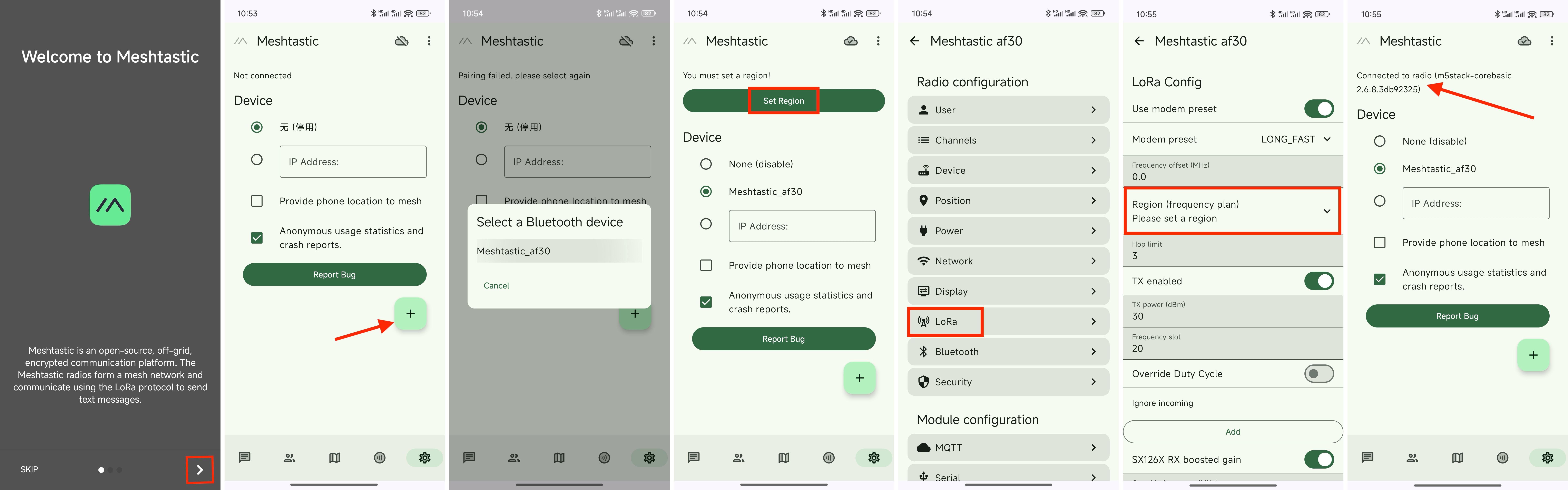
1. Install the Meshtastic app on Your Phone
Download the Meshtastic app from the Google Play or Download APK from GitHub(for Android) or App Store(for IOS).
2. Pair the Device
Open the Meshtastic app and follow the on-screen instructions to pair your device via Bluetooth—nearby devices will be detected automatically. The iOS and Android Meshtastic apps offer similar features but have different interfaces, so setup steps and screenshots are shown separately for each platform.
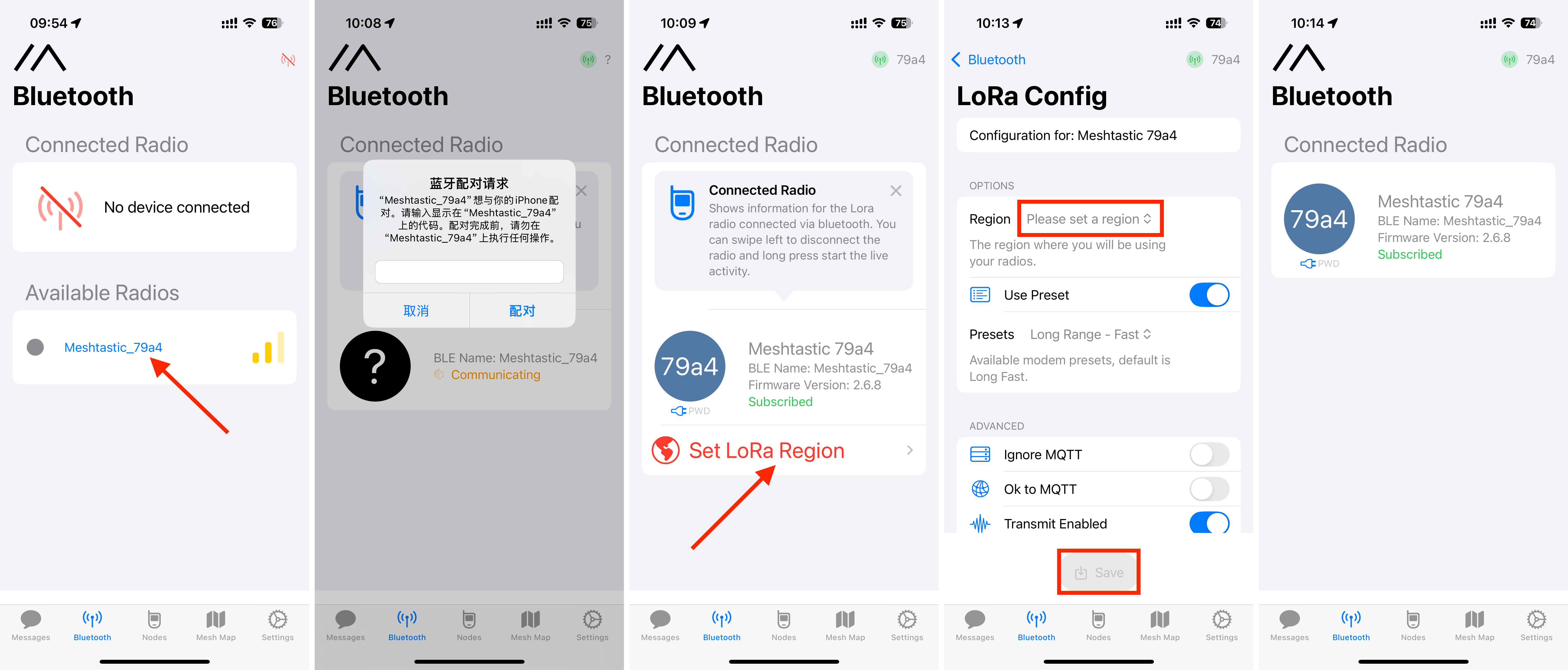
3. Configure Device Settings
After pairing, you could set the Lora region, select the appropriate region (e.g., EU 868MHz), username in the app.
When running Meshtastic, the ESP32 can't use Wi-Fi and Bluetooth simultaneously. Bluetooth is enabled by default. If you turn on Wi-Fi, Bluetooth will be disabled. To re-enable it, connect the device to your computer via USB and use the Meshtastic Web Client in Chrome to disable Wi-Fi.
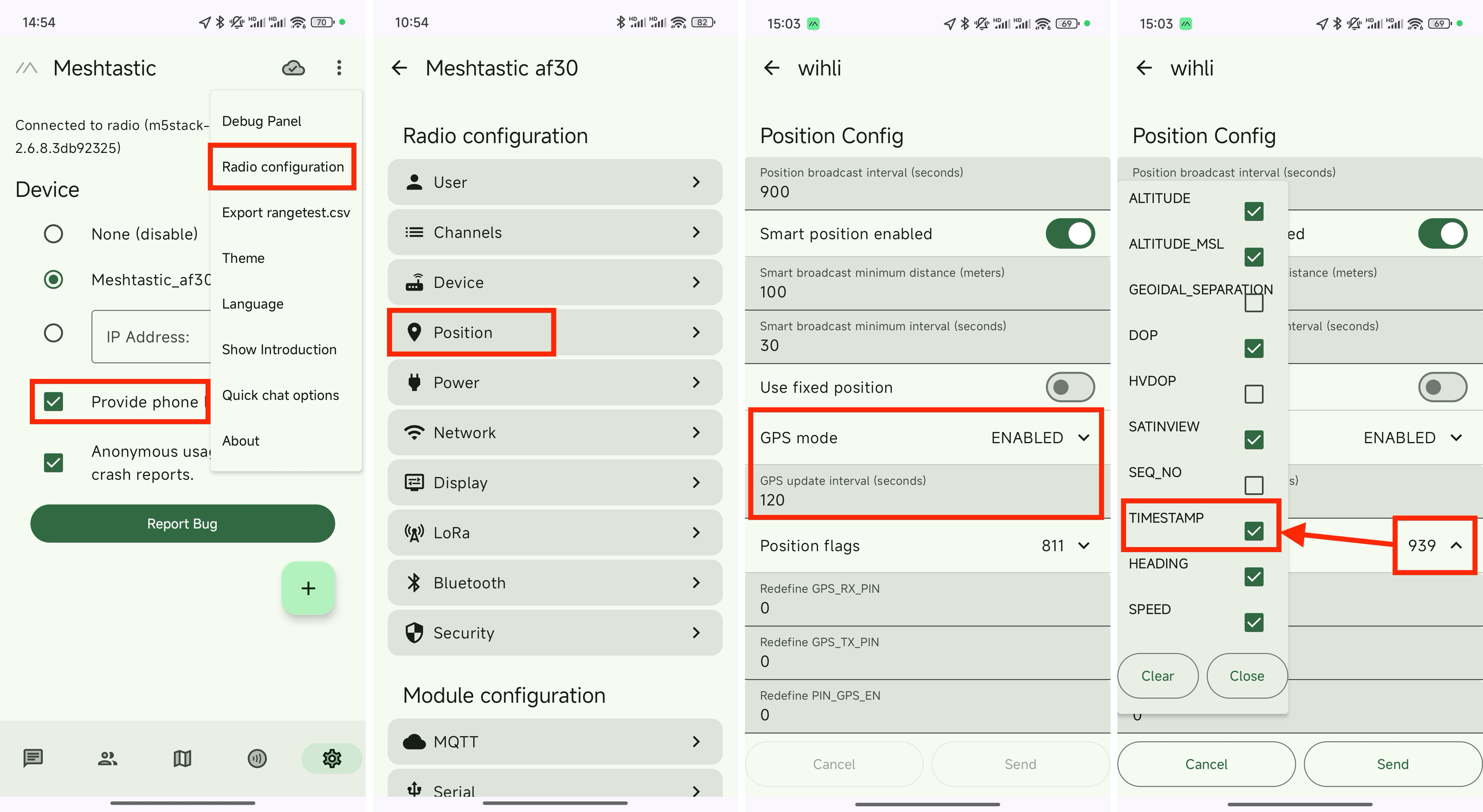
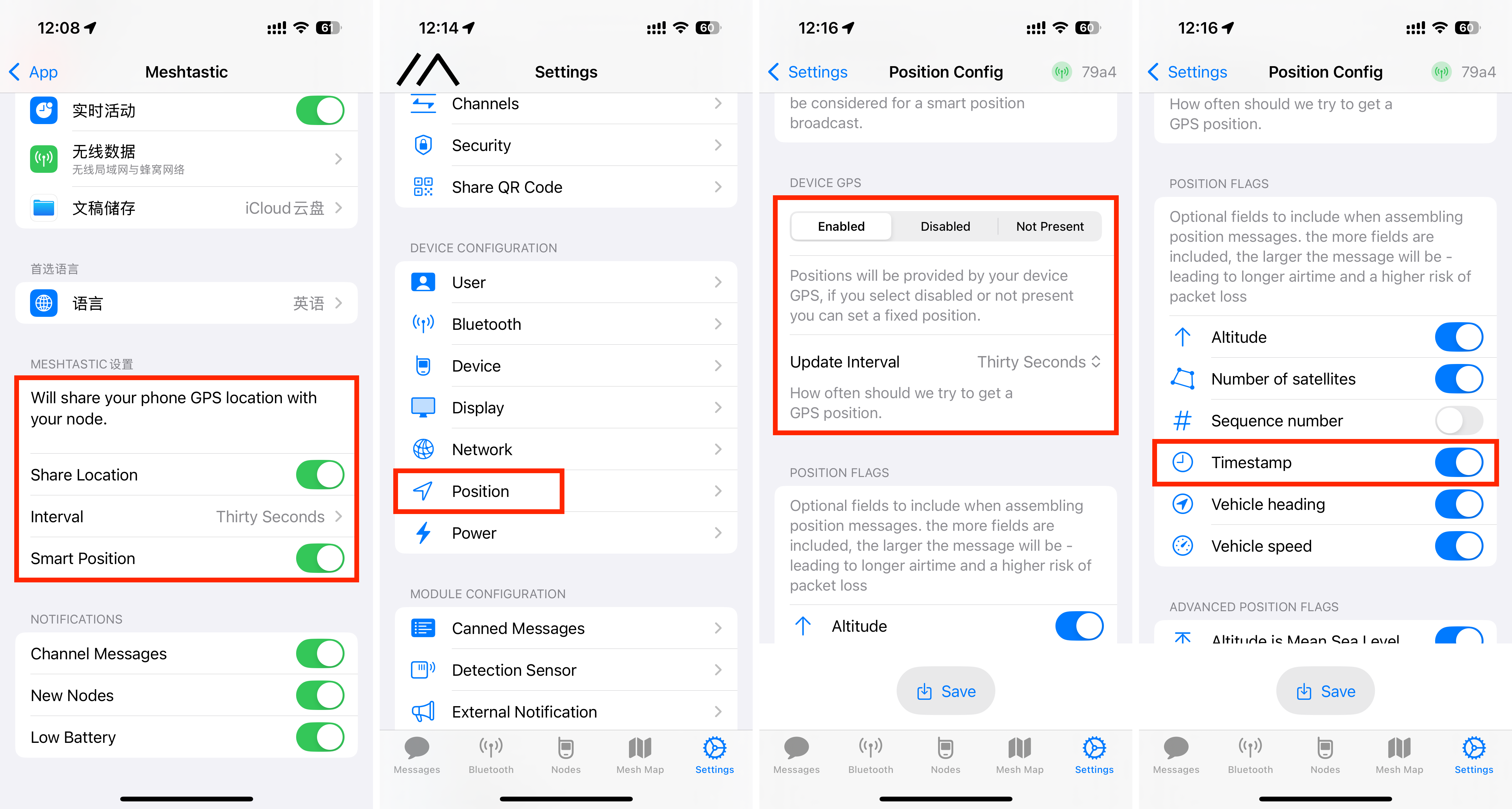
Step 4: Add GPS To Your Meshtastic Node
Core1/Core2 with LoRa868 v1.2 doesn’t have built-in GPS, but you can share your smartphone’s GPS location with the device. It's useful for team members to track each other during outdoor activities.
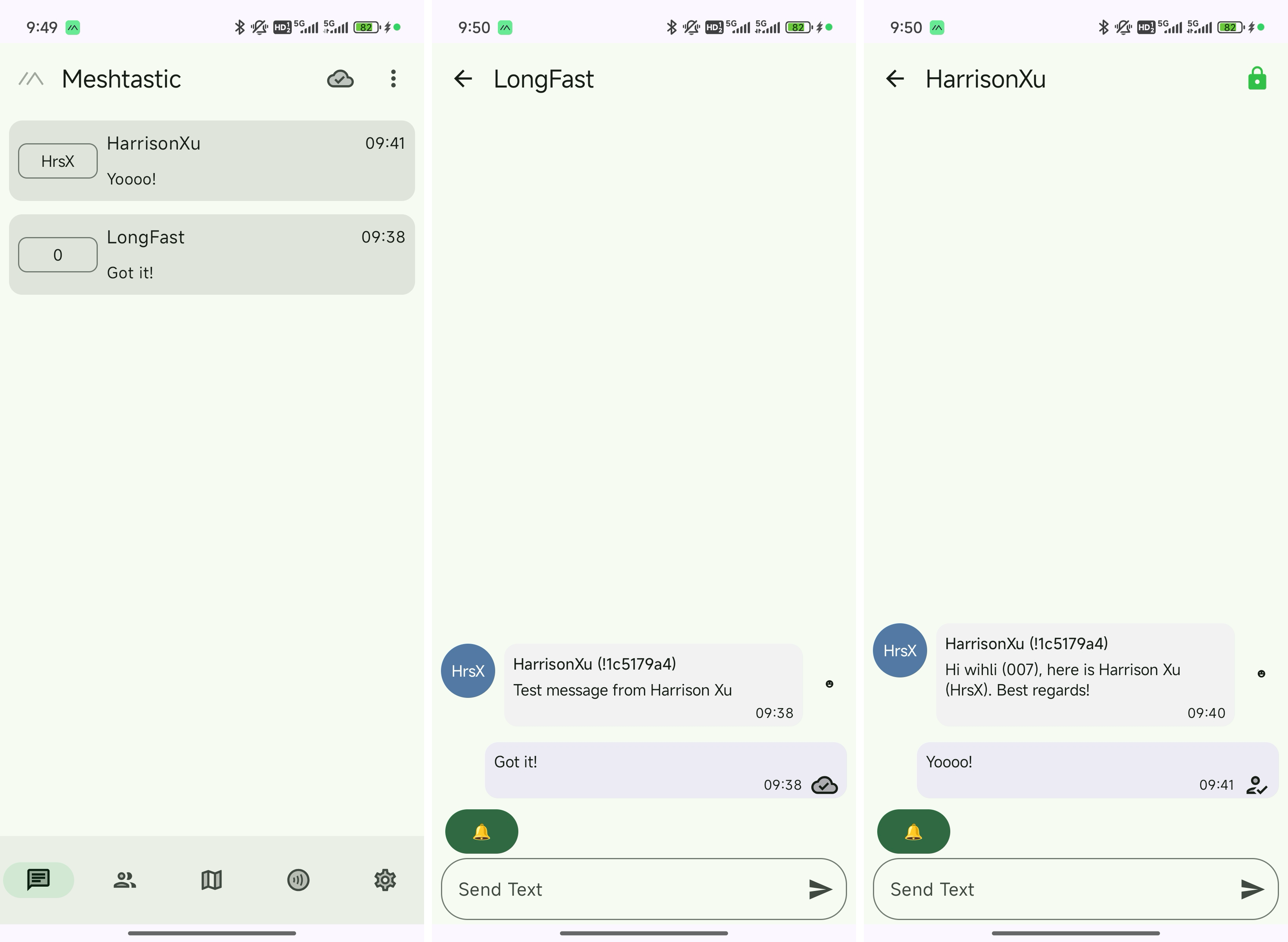
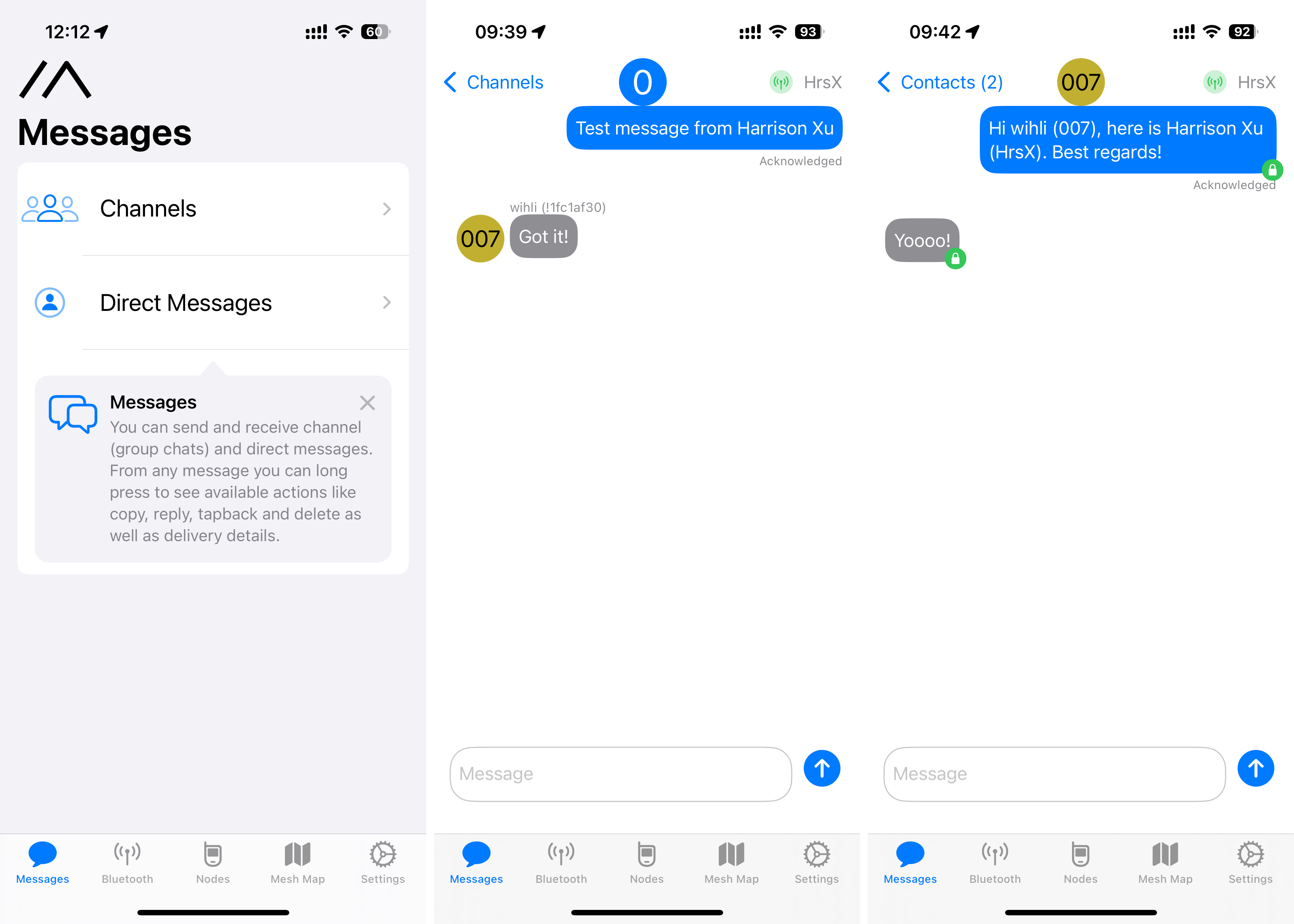
Step 5: Send and Receive Message
With other nodes show up in the list, you're connected to the mesh and can start messaging via the Meshtastic app.
Is Meshtastic Legal?
Yes, it’s legal. Meshtastic operates on license-free frequency bands such as 433 / 470 / 868 / 915 MHz which is in full compliance with FCC regulations.
How far does Meshtastic work?
The estimated range of this Meshtastic setup is around 4 km (2.49 miles). But the range between two Meshtastic nodes varies based on antenna setup, and environmental conditions. You may try moving the device around to test the range, check the signal to ensure stable connectivity.