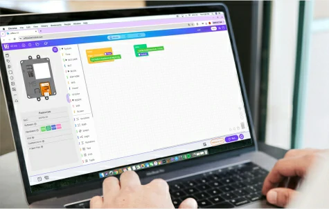
As Anthropic continues expanding Claude’s hardware interaction capabilities, experiences that once lived only on a computer screen can now be brought to life through compact hardware devices. AI is starting to evolve from a “helper inside the screen” into a true “companion on your desk”.

Among today’s most talked-about Claude hardware interaction projects, M5Stack devices have emerged as one of the most popular platforms among developers, with official recommendations from Claude. More and more makers are using M5Stack hardware to build their own Claude Desktop Buddy devices—small companions that can display Claude’s status, notify users when authorization is needed, respond to interactions, and even act like a desktop pet while you work.
Within the M5Stack ecosystem, several representative Claude Buddy approaches have already emerged.
Claude’s Official Demo: Claude Desktop Buddy with StickC Plus
One of the first projects to spark widespread interest was Anthropic’s official public demo: Claude Desktop Buddy, built with ESP32 & Arduino on the M5Stack StickC Plus.

GitHub: https://github.com/anthropics/claude-desktop-buddy
At its core, Claude Desktop Buddy is a desktop companion that connects to Claude Desktop via BLE. Once connected, the device reacts to Claude’s working state in real time:
· It stays calm while idle
· Wakes up when a conversation begins
· Shows an active working state while Claude is busy
· Alerts the user when authorization is required
· Allows approvals or rejections directly on the device
It is much more than a simple status indicator, for it behaves more like a desktop pet with personality. The project includes 18 built-in ASCII pet characters, each with multiple animation states. It also supports custom GIF character packs, making it easy for developers to create their own personalized Buddy. On top of that, it includes interactive behaviors such as:
· Shake detection
· Flip-to-sleep
· Automatic screen timeout
· LED alerts during authorization requests
Depending on Claude’s state, the Buddy can appear sleepy, idle, busy, waiting for attention, celebrating, dizzy, or even showing affection—making the interaction feel much more lively and expressive.
Getting started is also relatively straightforward. Developers can flash the firmware to the StickC Plus using PlatformIO, enable Developer Mode in Claude Desktop, open the Hardware Buddy window, and pair the device over Bluetooth. Once connected, the desktop app and hardware can automatically reconnect and continuously stay in sync.

It is no surprise that StickC Plus was chosen for Claude’s first official example. With its built-in screen, buttons, IMU, and BLE, it already covers nearly all the core requirements of a Claude Buddy without needing additional peripherals. Its compact form factor makes it easy to hold in your hand or place directly on your desk. It works well as a status display while also remaining convenient for quick interactions. If you want to quickly experience Claude Buddy, or build an eye-catching AI desk companion, StickC Plus is a highly recommended choice.
Recommended in Anthropic’s Developer Conference: Build with Claude on Cardputer-Adv
Besides the BLE-based desktop pet approach, another highly interesting direction comes from Anthropic’s developer conference, Build with Claude, where M5Stack Cardputer-Adv is used as the core device and has been well received by participating developers.
Compared with StickC Plus, which focuses more on desktop presence and status feedback, the Cardputer-Adv route emphasizes something different: letting Claude Code directly participate in the hardware creation process itself. In other words, Claude can help not only write applications, but also assist with flashing, deployment, and iteration.

More info: https://claude.com/code-with-claude/makers
Technically, this solution follows a UIFlow + MicroPython rapid development path, combined with Claude Code and related skills for setup and deployment. The project repository already includes scripts, Buddy app packages, and an extensible app directory. Developers can either run the existing project directly or continue adding their own .py applications to expand functionality over time. For anyone who wants to experience the idea of “AI helping me build hardware applications”, Cardputer-Adv is a very representative and exciting option.
Cardputer-Adv itself is also well suited to this role. With its built-in keyboard and screen, interaction feels more natural, whether for navigating menus, displaying Claude status, or running lightweight applications. Combined with the ESP32-S3’s connectivity and expandability, it naturally fits the concept of a portable AI mini terminal. It can become: a weather assistant, a pixel pet, a pocket utility tool, or simply your own personalized Claude Buddy.

One of the biggest advantages of this workflow is how direct it feels. You connect the Cardputer-Adv, open Claude Code, and enter “m5-onboard go”.
From there, the toolchain can automatically handle device detection, firmware flashing, app installation, rebooting, and startup. This makes it especially suitable for hackathons, workshops, and rapid prototyping sessions—bringing the vision of “build what you imagine” much closer to reality.
More M5Stack Devices Are Joining the Claude Desktop Buddy Ecosystem
Beyond these two examples, many other M5Stack host devices are also well suited to Claude Buddy-style projects. The community is already beginning to adapt related ideas to devices such as StickC Plus2, StickS3, Paper, and more.
A good Desktop Buddy needs to bring together display, interaction, connectivity, and local processing, and these are exactly the strengths shared by many M5Stack host devices. Whether it is from the Core, Stick, Atom, Cardputer, or E-Paper product lines, M5Stack offers a broad and mature hardware portfolio for developers to choose from.
For Claude Buddy-style applications, devices with a screen, buttons, or input methods, sensors, BLE, or Wi-Fi connectivity are naturally strong candidates.
 |
 |
 |
 |
M5Stack continues to be a go-to device for developers for several reasons:
· Ready to use out of the box — highly integrated and easy to develop with
· Low barrier to entry — support for multiple development platforms, including Arduino, UIFlow, ESP-IDF, MicroPython and more
· Great for visual presentation and demos — ideal for desktop setups, demos, workshops, exhibitions, and event showcases
· Complete hardware ecosystem — covering controllers, expansion modules, sensors, and accessories for fast prototyping and continuous expansion
· Large developer community — widely recognized by the global maker community, with abundant documentation and community resources
From Software Assistant to Physical Companion
The rise of Claude Buddy is just one example of how large-model AI is moving from the software world into the physical world. As more AI applications begin to leave the chat window and enter desktop devices, portable terminals, and real-world interaction scenarios, hardware is becoming an increasingly important bridge between AI and everyday life.
With its complete hardware ecosystem, highly integrated product design, and developer-friendly experience, M5Stack is becoming an important physical platform for developers around the world to connect large AI models with the real world. It is also opening up broader possibilities for AI desk companions, smart terminals, and innovative prototyping.

In the demanding landscape of industrial automation, reliability and adaptability are the benchmarks of success. The StamPLC, anchored by the high-performance Stamp-S3A module, is a specialized IoT controller engineered to bridge the divide between professional-grade logic control and the flexibility of the smart home. By bringing the StamPLC into your Home Assistant ecosystem via ESPHome, you gain access to an enterprise-level automation suite for everything from remote telemetry to high-voltage AC management. This guide provides a comprehensive walkthrough of the deployment process, from initial flashing to the configuration of specialized PoE and AC expansion modules.

Preparations
o A Home Assistant host
o Install and enable the ESPHome Builder add-on in Home Assistant
Open ESPHome Builder in Home Assistant and create an empty configuration file:
o Click the NEW DEVICE button at the bottom right
o In the dialog click CONTINUE
o Select Empty Configuration

o (Optional) Give the file a name
o Click EDIT on the newly created configuration file

o Then copy the contents of configuration.yaml from the example repository into your config file:

Modify network or API information as needed. For example, create an API Encryption Key for authentication:
api:
  encryption:
    key: "Your_Encryption_Key"
You can also change the timezone setting, for example:
timezone: America/Los_Angeles # Pacific
# timezone: America/New_York # Eastern
After editing, click SAVE and then INSTALL, choose Manual download.

This will generate code and compile the project.
When the build finishes, select Factory format to download the firmware.

Upload firmware
Open ESPHome Web in your browser to upload the firmware.
Connect StamPLC to the host via USB-C, click CONNECT and select the device.
Click INSTALL, select the previously downloaded firmware, and click INSTALL again to flash the device.
After flashing completes the device will automatically reset and boot.

Add device to Home Assistant Integrations
When the device boots it will connect to the configured Wi‑Fi. Under Settings -> Devices & services you should see the device.

Click Add to add StamPLC to Home Assistant. If you set an API Encryption Key, you may need to enter it here.
Example StamPLC dashboards:


Live device in action:

Expansion
The StamPLC support expansion via 16 pin headers on the right side of the device.

StamPLC AC is an AC relay expansion module compatible with the StamPLC host. The module integrates AC load control and entire system power supply functions, effectively simplifying power wiring during application development. It features a contact-type relay (single-pole single-throw - normally open), supporting up to AC 240V@10A line switching. It also includes a built-in AC-DC isolated conversion circuit supporting AC 100 ~ 240V input, capable of simultaneously powering the relay load and providing a stepped-down DC 12V output for the main system. A programmable tri-color RGB LED is available for working status indication.
Configure the StamPLC AC
In addition to previous StamPLC configurations, several components are required
o Add a new IO Expander
pi4ioe5v6408:
  - id: pi4ioe5v6408_1
    address: 0x43
  # Configuration of i2c GPIO Expander 2
  # on the StamPLC AC expansion
  - id: pi4ioe5v6408_2
    address: 0x44
o Add a new switch for AC Relay
switch:
  ...
  # led indicator on StamPLC AC expansion
  - platform: gpio
    restore_mode: ALWAYS_OFF
    id: "ac_relay_led_red"
    pin:
      pi4ioe5v6408: pi4ioe5v6408_2
      number: 5
      inverted: true
      mode:
        output: true

  - platform: gpio
    restore_mode: ALWAYS_OFF
    id: "ac_relay_led_green"
    pin:
      pi4ioe5v6408: pi4ioe5v6408_2
      number: 6
      inverted: true
      mode:
        output: true

  - platform: gpio
    restore_mode: ALWAYS_OFF
    id: "ac_relay_led_blue"
    pin:
      pi4ioe5v6408: pi4ioe5v6408_2
      number: 7
      inverted: true
      mode:
        output: true
o UI Update the UI display
display:
  ...
  lambda: |-
    ...
    it.print(5, 80, id(font1), Color(orange), "Relays 1-4");
    it.filled_rectangle(5, 99, 25, 25, id(r1).state ? id(red) : id(grey));
    it.filled_rectangle(34, 99, 25, 25, id(r2).state ? id(red) : id(grey));
    it.filled_rectangle(63, 99, 25, 25, id(r3).state ? id(red) : id(grey));
    it.filled_rectangle(92, 99, 25, 25, id(r4).state ? id(red) : id(grey));
    it.print(141, 80, id(font1), Color(orange), "AC Expansion");    // The AC Relay Expansion
    it.filled_rectangle(141, 99, 25, 25, id(ac_r1).state ? id(red) : id(grey));
  ...
When finishing the configuration, recompile and upload the firmware. Then, you should be able to control additional AC relay in your Home Assistant:

Turn on/off the switch, the UI element on LCD will change accordingly.


StamPLC PoE is an Ethernet control module designed for the StamPLC host. It supports PoE (Power over Ethernet) technology, enabling both data transmission and power supply through a single Ethernet cable. The module integrates a W5500 embedded Ethernet controller with a built-in TCP/IP protocol stack, providing 8 independent hardware sockets, a 10/100M Ethernet data link layer (MAC), and physical layer (PHY). It supports mainstream network communication methods such as UDP and TCP.
To enable PoE functionality, disable the wifi, display, and spi components (remove their declarations/definitions from the configuration file). Then add the following to the original configuration file:
ethernet:
  id: ethernet_1
  type: W5500
  clk_pin: GPIO7
  mosi_pin: GPIO8
  miso_pin: GPIO9
  cs_pin: GPIO11
  clock_speed: 20MHz
Save and install, then upload the firmware. Use a PoE switch or router to power the device while providing network connectivity.

Ready for Deployment
With the firmware flashed and your expansion modules configured, your StamPLC is no longer just a piece of hardware—it is now a sophisticated gateway for your automation needs. The beauty of this setup lies in its modularity; whether you are scaling up with StamPLC PoE for high-reliability data or utilizing StamPLC AC relays for heavy-duty switching, the combination with Home Assistant provides a unified, professional interface for it all.
Now that your foundation is built, you can move beyond basic setup and start creating the complex logic, schedules, and automations that make your industrial or home environment truly intelligent.

Introduction
The Chain DualKey is a programmable dual-button input development board. Its factory firmware allows you to configure button functions and RGB LED colors, as well as other Chain series devices connected via the Chain Bus.

Ready to unleash its full potential? This guide will walk you through everything from firmware flashing via M5Burner to advanced Web-based configuration. Master the core essentials in minutes and make your desktop setup smarter and more efficient.
Steps
1. Button Numbering
In the factory firmware, the two buttons on Chain DualKey are named Key1 (Left Key) and Key2 (Right Key):

2. Switch Positions
3. Connecting to Host as Keyboard
Chain DualKey can connect to two devices simultaneously — one via a wired connection and the other via Bluetooth.
4. Configuration Web Page
Power the Chain DualKey via an external power source or toggle the switch to left / right side. On your computer or smartphone, connect to the Wi-Fi access point (SSID: DualKey_XXXX (XXXX is a four-character alphanumeric code used to distinguish different devices), Password: 12345678), then open a browser and visit 192.168.4.1 to access the configuration web page:


5. Chain Bus
Chain DualKey can connect to other Chain series devices—such as Chain Key and Chain Joystick—through the Chain Bus on either side. (More Chain series devices will be released soon.)
Devices in the Chain series can be connected via Chain Bridge or Chain Return. When connecting, pay attention to the direction: the triangle arrow at the bottom of each device should point outward from the Chain DualKey (the main controller), as shown below:

At the bottom of the configuration web page, you can view and configure the functions of all devices connected to the Chain Bus:

Conclusion
With your Chain DualKey now fully configured, you are ready to enjoy a more intuitive and efficient desktop experience. From custom macros to vibrant RGB setups, this compact device is designed to evolve alongside your workflow. Stay tuned for more Chain series modules to further expand your creative setup!

Today, we are going to integrate the M5Stack TAB5 into Home Assistant (HA), a very interesting device for creating a portable control dashboard.
M5Stack Tab5
· Powered by an ESP32-P4 SoC, with 16MB of flash memory and 32MB of PSRAM. This makes it the device with the most memory we have integrated into Home Assistant to date.
· It features a generous 5″ TFT touchscreen (1280×720), compatible with LVGL.
· Includes a front-facing 2 MP SC2356 camera (1600×1200) for capturing images and video.
· Equipped with one USB-A port, one USB-C port, and a Micro SD card slot (card not included).
· It has two expansion ports for external sensors (GROVE and M5BUS) and a connector for a LoRa antenna.
· Features two microphones, a speaker, and a 3.5mm jack, meaning you can also use it to control Assist.
· If you chose the "TAB5 Kit," it comes with a Li-ion battery that you can easily replace (allowing you to have a spare one charged and ready).

In short, these characteristics make it the perfect candidate for a portable, autonomous control device with great tactile feedback. Additionally, as it is based on an ESP32-P4, the M5Stack TAB5 can be integrated into HA via ESPHome.
Prerequisites
To integrate the M5Stack TAB5 into HA, you will first need:
· Your M5Stack Tab5 (with or without the battery).
· To have ESPHome installed in Home Assistant.
· A USB-C DATA cable to power the board (you will not be able to install the software with a charge-only cable).
Configuration in ESPHome
Follow these steps to integrate the M5Stack TAB5 into HA:
1. In Home Assistant, go to your ESPHome add-on and click on New device > Continue > New Device Setup.
2. Give your device a name (for example, “M5stack Tab5”) and click “Next.”
3. For the device type, select “ESP32-C6.” You will notice in the background that a new block has been created for your device.
4. Click “Skip” and then click “Edit” on your device's block. Copy the code that appears and save it, as you will need parts of it later.
5. Copy the following code and use it to replace the previous code in ESPHome.
substitutions:

# Device customization
# Personalización del dispositivo

  name: m5stack-tab5
  friendly_name: M5stack Tab5

####################################

esphome:
  name: ${name}
  friendly_name: ${friendly_name}

esp32:
  board: esp32-p4-evboard
  flash_size: 16MB
  framework:
    type: esp-idf
    advanced:
      enable_idf_experimental_features: true

esp32_hosted:
  variant: esp32c6
  active_high: true
  clk_pin: GPIO12
  cmd_pin: GPIO13
  d0_pin: GPIO11
  d1_pin: GPIO10
  d2_pin: GPIO9
  d3_pin: GPIO8
  reset_pin: GPIO15
  slot: 1

logger:
  hardware_uart: USB_SERIAL_JTAG

psram:
  mode: hex
  speed: 200MHz

api:
  encryption:
    key: "F8WsdfddfKt1XvQV9pU32443dsfdsf"

ota:
  - platform: esphome
    password: "sdffds23b12747edfq43543"

wifi:
  ssid: !secret wifi_ssid
  password: !secret wifi_password
  ap:
    ssid: "M5Stack-Tab5 Fallback Hotspot"
    password: "sdfdMtQR34rfww"

# Sensors configuration
# Configuración de sensores

binary_sensor:
  - platform: gpio
    id: charging
    name: "Charging Status"
    pin:
      pi4ioe5v6408: pi4ioe2
      number: 6
      mode: INPUT_PULLDOWN

  - platform: gpio
    id: headphone_detect
    name: "Headphone Detect"
    pin:
      pi4ioe5v6408: pi4ioe1
      number: 7

i2c:
  - id: bsp_bus
    sda: GPIO31
    scl: GPIO32
    frequency: 400kHz

pi4ioe5v6408:
  - id: pi4ioe1
    address: 0x43
    # 0: O - wifi_antenna_int_ext
    # 1: O - speaker_enable
    # 2: O - external_5v_power
    # 3: NC
    # 4: O - lcd reset
    # 5: O - touch panel reset
    # 6: O - camera reset
    # 7: I - headphone detect
  - id: pi4ioe2
    address: 0x44
    # 0: O - wifi_power
    # 1: NC
    # 2: NC
    # 3: O - usb_5v_power
    # 4: O - poweroff pulse
    # 5: O - quick charge enable (inverted)
    # 6: I - charging status
    # 7: O - charge enable

select:
  - platform: template
    id: wifi_antenna_select
    name: "WiFi Antenna"
    options:
      - "Internal"
      - "External"
    optimistic: true
    on_value:
      - if:
          condition:
            lambda: return i == 0;
          then:
            - switch.turn_off: wifi_antenna_int_ext
          else:
            - switch.turn_on: wifi_antenna_int_ext

# The DAC Output select needs to be manually (or with an automation) changed to `LINE1` for the onboard speaker
  - platform: es8388
    dac_output:
      name: DAC Output
    adc_input_mic:
      name: ADC Input Mic

sensor:
  - platform: ina226
    address: 0x41
    adc_averaging: 16
    max_current: 8.192A
    shunt_resistance: 0.005ohm
    bus_voltage:
      name: Battery Voltage
    current:
      name: Battery Current
      # Positive means discharging
      # Negative means charging

switch:
  - platform: gpio
    id: wifi_power
    name: "WiFi Power"
    pin:
      pi4ioe5v6408: pi4ioe2
      number: 0
    restore_mode: ALWAYS_ON
  - platform: gpio
    id: usb_5v_power
    name: "USB Power"
    pin:
      pi4ioe5v6408: pi4ioe2
      number: 3
  - platform: gpio
    id: quick_charge
    name: "Quick Charge"
    pin:
      pi4ioe5v6408: pi4ioe2
      number: 5
      inverted: true
  - platform: gpio
    id: charge_enable
    name: "Charge Enable"
    pin:
      pi4ioe5v6408: pi4ioe2
      number: 7
  - platform: gpio
    id: wifi_antenna_int_ext
    pin:
      pi4ioe5v6408: pi4ioe1
      number: 0
  - platform: gpio
    id: speaker_enable
    name: "Speaker Enable"
    pin:
      pi4ioe5v6408: pi4ioe1
      number: 1
    restore_mode: ALWAYS_ON
  - platform: gpio
    id: external_5v_power
    name: "External 5V Power"
    pin:
      pi4ioe5v6408: pi4ioe1
      number: 2

# Display configuration
# Configuración de la pantalla

esp_ldo:
  - voltage: 2.5V
    channel: 3

font:
  - file: "gfonts://Kanit"
    id: font_title
    size: 100

light:
  - platform: monochromatic
    output: backlight_pwm
    name: "Display Backlight"
    id: backlight
    restore_mode: RESTORE_DEFAULT_ON
    default_transition_length: 250ms

output:
  - platform: ledc
    pin: GPIO22
    id: backlight_pwm
    frequency: 1000Hz

touchscreen:
  - platform: gt911
    interrupt_pin: GPIO23
    update_interval: never
    reset_pin:
      pi4ioe5v6408: pi4ioe1
      number: 5
    calibration:
      x_min: 0
      x_max: 720
      y_min: 0
      y_max: 1280
    id: touch

display:
  - platform: mipi_dsi
    dimensions:
      height: 1280
      width: 720
    model: M5Stack-Tab5
    reset_pin:
      pi4ioe5v6408: pi4ioe1
      number: 4
    show_test_card: true
    rotation: 90

lvgl:
  touchscreens: touch
  buffer_size: 100%
  style_definitions:
    - id: style_title
      align: CENTER
      text_font: font_title
  widgets:
    - label:
        styles: style_title
        text: 'Hola Aguacater@s!!'

# Media configuration and voice assistant
# Configuración multimedia y asistente de voz

audio_dac:
  - platform: es8388
    id: es8388_dac

audio_adc:
  - platform: es7210
    id: es7210_adc
    bits_per_sample: 16bit
    sample_rate: 16000

i2s_audio:
  - id: mic_bus
    i2s_lrclk_pin: GPIO29
    i2s_bclk_pin: GPIO27
    i2s_mclk_pin: GPIO30

media_player:
  - platform: speaker
    name: None
    id: speaker_player
    announcement_pipeline:
      speaker: tab5_speaker
      format: FLAC
      sample_rate: 48000
      num_channels: 1
    on_announcement:
      # Stop the wake word (mWW or VA) if the mic is capturing
      - if:
          condition:
            - microphone.is_capturing:
          then:
            - micro_wake_word.stop:
    on_idle:
      # Since VA isn't running, this is the end of user-intiated media playback. Restart the wake word.
      - if:
          condition:
            not:
              voice_assistant.is_running:
          then:
            - micro_wake_word.start:

micro_wake_word:
  id: mww
  models:
    - okay_nabu
    - hey_mycroft
    - hey_jarvis
  on_wake_word_detected:
    - voice_assistant.start:
        wake_word: !lambda return wake_word;

microphone:
  - platform: i2s_audio
    id: tab5_microphone
    i2s_din_pin: GPIO28
    sample_rate: 16000
    bits_per_sample: 16bit
    adc_type: external

# Commented out to avoid duplicates (see above)
# Comentado para evitar duplicidades (ver arriba)
#select:
# The DAC Output select needs to be manually (or with an automation) changed to `LINE1` for the onboard speaker
#  - platform: es8388
#    dac_output:
#      name: DAC Output
#    adc_input_mic:
#      name: ADC Input Mic

speaker:
  - platform: i2s_audio
    id: tab5_speaker
    i2s_dout_pin: GPIO26
    audio_dac: es8388_dac
    dac_type: external
    channel: mono
    buffer_duration: 100ms
    bits_per_sample: 16bit
    sample_rate: 48000

voice_assistant:
  id: va
  microphone: tab5_microphone
  media_player: speaker_player
  micro_wake_word: mww
  on_end:
    # Wait a short amount of time to see if an announcement starts
    - wait_until:
        condition:
          - media_player.is_announcing:
        timeout: 0.5s
    # Announcement is finished and the I2S bus is free
    - wait_until:
        - and:
            - not:
                media_player.is_announcing:
            - not:
                speaker.is_playing:
    - micro_wake_word.start:
  on_client_connected:
    - micro_wake_word.start:
  on_client_disconnected:
    - micro_wake_word.stop:
6. Important note: This code does not include the credentials required for the device to connect to your WiFi and your Home Assistant instance, so you must add them manually. Specifically, I am referring to the following lines from the code you copied in step 4.
# Enable Home Assistant API
api:
  encryption:
    key: "bg6hash6sjdjsdjk02hh0qnQeYVwm123vdfKE8BP5"

ota:
  - platform: esphome
    password: "asddasda27aab65a48484502b332f"

wifi:
  ssid: !secret wifi_ssid
  password: !secret wifi_password

  # Enable fallback hotspot (captive portal) in case wifi connection fails
  ap:
    ssid: "Assist Fallback Hotspot"
    password: "ZsasdasdHGP2234"
7. What you need to do is find the corresponding lines in the code (at the beginning) and add the relevant information.
8. Now, click "Save" and "Install." Select "Manual download" and wait for the code to compile.
9. Once finished, select the "Modern format" option to download the corresponding '.bin' file.
10. Connect the M5Stack TAB5 to your computer using the USB-C data cable via the side port.
11. Now go to the ESPHome Web page and click "Connect." In the pop-up window, select your board and click "Connect."
12. Now click "Install" and select the '.bin' file obtained in step 9. Click "Install" once more.
13. Return to Home Assistant and go to Settings > Devices & Services. Your device should normally be discovered and appear at the top, simply waiting for you to click the "Configure" button. Otherwise, click the "Add Integration" button, search for "ESPHome," and enter your board's IP address in the "Host" field. As always, I recommend that you assign a static IP in your router to avoid future issues if it changes.
14. Finally, go to Settings > Devices & Services > ESPHome. Click the "Configure" link for your device. In the pop-up window, check the box "Allow the device to perform Home Assistant actions" and click "Submit." This will allow us to control our devices directly from the screen.
If everything went well, you should see the following on your screen:

Additionally, with this code, you will be able to:
· Control and monitor the device's sensors in Home Assistant (such as battery percentage, activating the speaker, turning on the screen…).
· Use the screen to create your control dashboard and manage your devices.
· Expose your M5Stack Tab5 as a media player entity, allowing you to use it to play audio notifications or the radio.
· Use it as a voice assistant if you have already configured Assist.
From here on, the way you use the panel depends on your imagination!
Source: AguacaTEC
Author: TitoTB

Hardware and Design
The Cardputer-Adv is an enhanced iteration of the small-form-factor computer powered by the Espressif ESP32-S3 microcontroller. In essence, the Cardputer-Adv is a slightly redesigned version of the original. Side-by-side, they differ visually only in color—the new model is white, while the previous was light gray. The shape, design, and general purpose remain identical. The "brain" of the system is still a Stamp series development board, but upgraded to the Stamp-S3A. Compared to the Stamp-S3 found in the predecessor, the "A" revision features a redesigned 3D antenna for improved connectivity and a "softer," more responsive Reset button. Note that this button is covered by a sticker, making it somewhat awkward to press. Other changes include internal LED wiring and lower power consumption. The core remains the ESP32-S3FN8 microcontroller with 8MB of Flash and 23 GPIO pins. As we have covered the ESP32-S3 extensively in previous articles, we will not repeat those technical details here. The USB-C port is used for programming the Stamp, power delivery, and charging the integrated battery.
Display, Keyboard, and Audio
The Stamp-S3A connects to the motherboard via two header rows and interfaces with the display via an FPC connector. The screen is the same color IPS LCD used previously (ST7789V2, 240×135 resolution, 1.14 inches). A defining feature of this computer is its 4×14 (56 keys) QWERTY keyboard. The keys are significantly improved with a different tactile feel (260gf vs. 160gf actuation force). Many keys serve dual purposes via 'Fn', 'Aa', 'Ctrl', 'Opt', and 'Alt' modifiers. Keyboard scanning is now handled by the TCA8418 integrated circuit.
The audio subsystem has undergone significant changes. The ES8311 codec replaces the previous NS4168 and SPM1423 combination, resulting in superior microphone noise reduction. Combined with the NS4150B amplifier and a 1W speaker (located standardly beneath the Stamp), the output quality is markedly better. Furthermore, the Cardputer-Adv now includes a 3.5mm audio jack on the side for headphone connectivity.

Power and Connectivity
The Cardputer-Adv can be powered via USB-C or the internal battery. This version replaces the two smaller cells of the original with a single, larger 1750mAh battery, managed by the TP4057 charging IC. Like its predecessor, the Cardputer-Adv features a GROVE port (supporting I2C and 5V). A small adjacent switch allows the user to toggle the 5V line direction: the Cardputer can either power an external sensor or be powered by an external source.
While the original Cardputer relied solely on the GROVE port for expansion, the Cardputer-Adv introduces an additional 2×7-pin header (UART, I2C, SPI) on the rear for connecting peripheral devices. M5Stack continues to use the GROVE connector for its extensive ecosystem of "Unit" expansion modules.
Sensors and Modules
New features include the BMI270 six-axis motion sensor (IMU). The device retains the physical power switch, 'Boot' and 'Reset' buttons, an infrared (IR) LED, and a Micro-SD slot. Examining the PCB reveals a layout largely identical to the original; it even retains an unpopulated JST connector for a smaller battery. Interestingly, there is an unconnected FPC connector near the 3.5mm jack for which we found no official documentation. The Cardputer-Adv maintains its Lego-compatible mounting holes (though there is one row fewer on the back) and internal magnets, allowing it to be mounted on metal surfaces like a refrigerator door.
Along with the Cardputer-Adv, we received the CAP LoRa868 (now the updated version is Cap LoRa-1262) expansion module, designed to interface via the 2×7-pin header. The CAP module features a matching plastic enclosure and contains two primary components: an 868MHz LoRa module (based on the SX1262 chip) with an SMA connector for an external antenna, and an AT6668-based GNSS module supporting GPS, Beidou (BD2/BD3), GLONASS, Galileo, and QZSS.

|
|
Software and Programming
The Cardputer-Adv can be programmed using Arduino IDE, ESP-IDF, PlatformIO, or the manufacturer-recommended UiFlow2. UiFlow2 is a block-based visual programming environment, making it an excellent educational tool for introducing children to microcontrollers and electronics. The interface offers "Blocks," "Split," and "Python" views. In "Split" mode, users can see how dragging blocks generates real-time Python code—a bridge that helps beginners transition to text-based programming. To use this online tool, the UiFlow2 firmware must first be flashed onto the device using the M5Burner utility.
Several pre-configured examples are available via M5Burner, including community-driven projects. One highlight is Meshtastic for Cardputer-Adv, which integrates seamlessly with the Meshtastic mobile app for LoRa-based mesh networking and precise GPS mapping. The firmware provides a comprehensive menu for managing hardware segments like LoRa, GPS, and system time.

Conclusion
Additional examples include M5Launcher, which allows users to execute BIN files directly from the Micro-SD card. The factory demo provides a comprehensive hardware test. For those using the Arduino environment, extensive support is available via M5Stack libraries.
The Cardputer-Adv is exactly what its name suggests: a sophisticated, credit-card-sized computer with meaningful upgrades over the original. The CAP expansion module (e.g., Cap LoRa-1262) is a powerful addition, and the new 2×7-pin header opens endless possibilities for hardware hackers.
Source: SK LABS
Author: Dejan Petrovic

When using M5Stack Modules or Bases, many users run into a common problem:
The same module, when stacked on different controllers (such as Basic, Core2, CoreS3, Tab5, etc.), uses different pin definitions. So, how should you correctly configure the pin numbers in your code?
If you have the same question, then understanding how the M5-Bus and DIP switches work is crucial.
This article will explain in a clear and practical way:
By the end, you could have a much clearer idea of how to set the DIP switches on the module, and how to configure the corresponding pin numbers in your program.
|
|
|
|
|
M5-Bus is a stack expansion bus design adopted by M5Stack stacking series products (Module, Base). The interface uses 2x15P@2.54mm pin headers/sockets. The Core series controllers can quickly stack different modules via the M5-Bus to achieve functional expansion. Its fixed positions define power pins such as GND, 5V, 3V3, and BAT, ensuring compatibility with various devices; other pins vary depending on the controller model, so you need to configure your program according to the actual pin mapping.
2. Fixed Function Pins
The pin numbers of M5-Bus are fixed starting from the GND pin at the top left corner, numbered from 1 to 30. This sequence is consistent across all controllers. The pins marked with a red box are fixed-function pins (power and GND, etc.), while other pins may have different functions or GPIO mappings depending on the main controller.
3. What is a DIP Switch
A DIP Switch is a toggle switch. It is used to flexibly change the connection of key module pins to adapt to different controller models. For example, in the case of Module GPS v2.0, there are three switchable pins: TXD, RXD, and PPS. Two onboard DIP switches control which pins these signals are connected to.
DIP Switch1’s switches 1–4 control TXD, switches 5–8 control RXD; DIP Switch2 is used to control PPS.
To avoid pin conflicts, typically each function pin only needs to be switched to one pin based on actual usage requirements. For example, in the following configuration, the 1st and 5th switches on DIP Switch1 are set to ON, the 2nd switch on DIP Switch2 is set to ON, and all other switches are set to OFF.
Based on the PCB silkscreen reference:
When programming the device, you must modify the corresponding pin configuration according to the actual pin connections.
The DIP switch’s corresponding positions and numbering connected to the M5-Bus are fixed (indicated by blue box).
If the PCB silkscreen’s I/O reference table does not include the controller model you are currently using, you can refer to the existing device’s silkscreen PinMap to identify which M5-Bus pins the DIP switch connects to, and then map those to the corresponding pins of your current controller.
When using Module LoRa868 with Tab5, and the DIP switches are set as shown in the picture, which Tab5 pins are used for NSS, BUSY, RST, and IRQ, respectively?
Answer

5. Wrapping Up:
Treat the DIP Switch as a “Hardware-Level Remapping Tool”
A DIP switch essentially gives you a form of hardware-level pin remapping:
The same module can be used with different Controllers, while routing key signals (TXD, RXD, PPS, etc.) to the most suitable GPIO pins.
In practice, if the module’s silkscreen or documentation already specifies how to set the DIP switches and which pins to use for your controller (for example, Core2, CoreS3), you can simply:
If your host controller is not listed, you can follow this simple procedure:
Once you understand this workflow, you no longer need to memorize which module “must be used with which Controller.”
Instead, you can flexibly migrate and reuse modules across different controllers, according to your actual needs.

Setting up a voice assistant doesn’t have to be complicated. At M5Stack, we’re proud to bring this capability closer to developers and makers with the M5Stack CoreS3—a powerful ESP32-S3 based controller with integrated display, rich interfaces, and cutting-edge performance.

With M5Stack CoreS3, you can seamlessly integrate advanced voice control into your Home Assistant ecosystem, enjoy real-time responsiveness, and experience true local AI interaction—secure, reliable, and fast.
The following guide walks you step-by-step through the process of setting up the CoreS3 HA Voice Assistant, from environment installation to voice activation.


Open the ESPHome addon page and click NEW DEVICE in the lower-right corner to create a new device.
Click CONTINUE.
Select New Device Setup to create a new configuration file.
Give the configuration file a proper name.
Next, when selecting the device, cancel the Use recommended settings, then select ESP32-S3. Locate M5Stack CoreS3 among the list.
Copy the Home Assistant API Encryption Key for later use, then click Skip
3.Configuring the Device
Click EDIT in the lower-left corner of the device to modify the Wi-Fi connection configuration. (The Wi-Fi configuration defaults to the current HA server's Wi-Fi settings, but you can also modify it directly with plaintext: ssid:"xxxx")
 Add the following package configuration link to add voice assistant functionality to the device.
packages:
  m5stack.cores3-voice-assistant: github://m5stack/esphome-yaml/common/cores3-satellite-base.yaml@main

Click SAVE and then INSTALL in the upper-right corner.
Select Manual Download to start compiling the firmware.
4.Firmware Flashing
Saving the Firmware


Connect the CoreS3 device to your computer via a USB-C cable and press and hold the reset button until the green light turns on, then release it to enter download mode.
In ESPHome Web, click Connect to connect to the device and select the corresponding device port.

Click INSTALL, upload the *.bin file previously compiled
Click INSTALL again to begin flashing
Wait until the flash is successful

5.Confirming the New Device Configuration
After firmware flashing, the device will automatically connect to Wi-Fi. The Home Assistant service within the same local network will prompt for a new device discovery. In Notifications, select the new device and click Check it out -> CONFIGURE, then follow the pop-up steps to add the device to the specified area to complete the configuration. If you do not receive a new device notification, click Settings -> Devices & services to view device status.

Then, you should be able to configure your Voice Assistant, or you can skip it and configure later
6.Waking Up the Device
After adding the device and completing the preparation steps for Home Assistant Cloud and Assist pipeline, you can now wake up the device using voice commands.
Demo video
With the steps above, your M5Stack CoreS3 has transformed into a fully functional Home Assistant voice terminal. Whether you use it to control lighting, monitor your environment, or communicate with other smart devices, CoreS3 bridges the gap between you and your smart home—bringing natural voice control to your fingertips.
M5Stack continues to empower developers with open, powerful, and beautifully designed hardware.
With CoreS3, you’re not just installing firmware—you’re giving your smart home a voice.

In today’s rapidly advancing world of intelligent applications, image and video management is evolving at an unprecedented pace.
Imagine capturing breathtaking travel landscapes or precious moments of your child’s growth — and having your photos automatically categorized, tagged, and searchable via natural language. All processing happens locally, with no dependence on cloud servers, ensuring both speed and privacy. With the powerhouse performance of the M5Stack LLM‑8850 Card, bring your vision to life with an intelligent, deeply personalized photo album that’s uniquely yours.

M5Stack LLM‑8850 Card is an M.2 M‑Key 2242 AI accelerator card designed for edge devices. It is a powerful yet energy-efficient AI edge computing module, purpose-built for multi-modal large models, on-device inference, and intelligent analysis. It delivers high-performance inference for both language and vision models, and can be deployed effortlessly across diverse devices to enable offline, private AI services.
In this article, we’ll show you how to build an intelligent photo management platform with M5Stack LLM-8850 Card, making the organization of your pictures and videos smarter, faster, and more secure.
To achieve this, we’ll leverage Immich, an open‑source self‑hosted photo and video management platform that supports automatic backup, intelligent search, and cross‑device access.
Immich is an open-source self-hosted photo and video management platform that supports automatic backup, intelligent search, and cross-device access.
1. Manually download the program and upload it to raspberrypi5, or pull the model repository with the following command.
git clone https://huggingface.co/AXERA-TECH/immich
File Description:
m5stack@raspberrypi:~/rsp/immich $ ls -lh
total 421M
drwxrwxr-x 2 m5stack m5stack 4.0K Oct 10 09:12 asset
-rw-rw-r-- 1 m5stack m5stack 421M Oct 10 09:20 ax-immich-server-aarch64.tar.gz
-rw-rw-r-- 1 m5stack m5stack    0 Oct 10 09:12 config.json
-rw-rw-r-- 1 m5stack m5stack 7.6K Oct 10 09:12 docker-deploy.zip
-rw-rw-r-- 1 m5stack m5stack 104K Oct 10 09:12 immich_ml-1.129.0-py3-none-any.whl
-rw-rw-r-- 1 m5stack m5stack 9.4K Oct 10 09:12 README.md
-rw-rw-r-- 1 m5stack m5stack  177 Oct 10 09:12 requirements.txt
unzip docker-deploy.zip
cp example.env .env
4. Start the container
docker compose -f docker-compose.yml -f docker-compose.override.yml up -d
If started successfully, the information is as follows:
m5stack@raspberrypi:~/rsp/immich $ docker compose -f docker-compose.yml -f docker-compose.override.yml up -d
WARN[0000] /home/m5stack/rsp/immich/docker-compose.override.yml: the attribute `version` is obsolete, it will be ignored, please remove it to avoid potential confusion
[+] Running 3/3
 ✔ Container immich_postgres  Started                                      1.0s
 ✔ Container immich_redis     Started                                      0.9s
 ✔ Container immich_server    Started                                      0.9s
(mich) m5stack@raspberrypi:~/rsp/immich $ python -m immich_ml
[10/10/25 09:50:12] INFO     Starting gunicorn 23.0.0
[10/10/25 09:50:12] INFO     Listening at: http://[::]:3003 (8698)
[10/10/25 09:50:12] INFO     Using worker: immich_ml.config.CustomUvicornWorker
[10/10/25 09:50:12] INFO     Booting worker with pid: 8699
2025-10-10 09:50:13.589360675 [W:onnxruntime:Default, device_discovery.cc:164 DiscoverDevicesForPlatform] GPU device discovery failed: device_discovery.cc:89 ReadFileContents Failed to open file: "/sys/class/drm/card1/device/vendor"
[INFO] Available providers:  ['AXCLRTExecutionProvider']
/home/m5stack/rsp/immich/mich/lib/python3.11/site-packages/immich_ml/models/clip/cn_vocab.txt
[10/10/25 09:50:16] INFO     Started server process [8699]
[10/10/25 09:50:16] INFO     Waiting for application startup.
[10/10/25 09:50:16] INFO     Created in-memory cache with unloading after 300s
                             of inactivity.
[10/10/25 09:50:16] INFO     Initialized request thread pool with 4 threads.
[10/10/25 09:50:16] INFO     Application startup complete.
In your browser, enter the Raspberry Pi IP address and port 3003, for example: 192.168.20.27:3003
Note: The first visit requires registering an administrator account; the account and password are saved locally.

Once configured, you can upload images.

The first time, you need to configure the machine learning server. Refer to the diagram below to enter the configuration.

Set the URL to the Raspberry Pi IP address and port 3003, e.g., 192.168.20.27:3003.
If using Chinese search for the CLIP model, set it to ViT-L-14-336-CN__axera; for English search, set it to ViT-L-14-336__axera.

After setup, save the configuration.

The first time, you need to manually go to the Jobs tab and trigger SMART SEARCH.

Enter the description of the image in the search bar to retrieve relevant images.

Through this hands-on project, we’ve not only built a powerful smart photo album platform, but also experienced the exceptional performance of the M5Stack LLM‑8850 Card in edge AI computing. Whether setting up a private photo album on your Raspberry Pi or deploying intelligent image processing in security scenarios, the M5Stack LLM‑8850 Card delivers efficient, stable computing power you can rely on.
It brings AI closer to where your data resides, enabling faster, more secure processing and turning your ideas into reality. If you’re looking for a solution for on-device AI inference, give M5Stack LLM‑8850 Card a try — it might just become the core engine of your next project.

If you've been wanting to use your devices remotely for a while, today you'll learn how to do it by integrating LoRa into Home Assistant.
Index
l What is LoRa and how does it work?
l Prerequisites
l Mounting and configuring the LoRa Gateway
l LoRa node configuration
l Check the communication
l Sending information
l Customize your Gateway
l Acknowledgments
What is LoRa and how does it work?
LoRa (an acronym for "Long Range") is a radio frequency communication protocol that enables long-distance data transmission (up to 10 km in open fields) with very low power consumption. Therefore, it offers two major advantages:
However, it also has its limitations, as its data transfer speed is slow. In practice, this means it's perfect for sending simple data (commands to our devices, numbers, or text strings), but it's not a suitable protocol for transmitting photos or videos.
Additionally, you should consider the frequency LoRa uses in your geographic area. For example, in Europe it's 868 MHz, while in the US and most of Latin America it's 915 MHz.
Prerequisites
To integrate LoRa into Home Assistant, you will need the following components:
|
|
|
|
Mounting and configuring the LoRa Gateway
We are going to be using the M5Stack Core S3 SE along with the LoRa868 V1.1 module (now the LoRa868 v1.2 module is available). This is a modular device that's very easy to expand by simply assembling the components.

Something important to keep in mind is that the LoRa module has some small switches on the back ('DIP switches') that modify the pin assignment, and logically, it must match what we indicate in the ESPHome code.
To do this, make sure the switches are in the following position (2, 6 and 7 on and the rest off).

From here, the process will be similar for any compatible motherboard (adapting the steps and connection diagram to the specifications of your device). The steps we followed are as follows:
1. In Home Assistant, go to your ESPHome plugin , tap “New device” and “Continue.”
2. Give your device a name (for example, “LoRa Gateway” ) and click “Next”.
3. Select “ESP32-S3” as the device type . You'll notice that a new block has been created for your device in the background.
4. Click “Skip” and click “Edit” above your device block.
5. Add the following lines to the end of your code (which come directly from the ESPHome SX127x component, adapted to our device).
captive_portal:

spi:
  clk_pin: GPIO36
  mosi_pin: GPIO37
  miso_pin: GPIO35

sx127x:
  cs_pin: GPIO6
  rst_pin: GPIO7
  dio0_pin: GPIO10
  pa_pin: BOOST
  pa_power: 14
  bandwidth: 125_0kHz
  crc_enable: true
  frequency: 868920000
  modulation: LORA
  rx_start: true
  sync_value: 0x12
  spreading_factor: 7
  coding_rate: CR_4_5
  preamble_size: 8
  on_packet:
    then:
      - lambda: |-
          ESP_LOGD("lambda", "packet %s", format_hex(x).c_str());
          ESP_LOGD("lambda", "rssi %.2f", rssi);
          ESP_LOGD("lambda", "snr %.2f", snr);

button:
  - platform: template
    name: "Transmit Packet"
    on_press:
      then:
        - sx127x.send_packet:
            data: [0xC5, 0x51, 0x78, 0x82, 0xB7, 0xF9, 0x9C, 0x5C]
6. Click “Save” and “Install.” Select “Manual download” and wait for the code to compile.
7. When finished, select the “Modern format” option to download the corresponding '.bin' file.
8. Connect the M5Stack Core S3 SE to your computer using the USB-C data cable via the port on the side.
9. Now go to the ESPHome page and click "Connect." In the pop-up window, select your board and click "Connect."
10. Now click on “Install” and select the '.bin' file obtained in step 7. Again, click on “Install”.
11. Return to Home Assistant and go to Settings > Devices & Services. Your device should have been discovered and appear at the top, waiting for you to press the "Configure" button. Otherwise, click the "Add integration" button, search for "ESPHome," and enter your board's IP address in the "Host" field. As always, we recommend assigning a static IP address to your router to avoid future issues if it changes.
LoRa node configuration
Now that we have our LoRa gateway, let's configure a node to send information to it. To do this, we'll follow steps very similar to those in the previous section:
1. In Home Assistant, go to your ESPHome plugin , tap “New device” and “Continue.”
2. Give your device a name (for example, “LoRa Node” ) and click “Next”.
3. Select “ESP32” as the device type . You'll notice a new block has been created for your device in the background.
4. Click “Skip” and click “Edit” above your device block.
5. Add the following lines to the end of your code (which in this case match the example of the SX127x component of ESPHome).
captive_portal:

spi:
  clk_pin: GPIO5
  mosi_pin: GPIO27
  miso_pin: GPIO19

# Example configuration entry
sx127x:
  cs_pin: GPIO18
  rst_pin: GPIO23
  dio0_pin: GPIO26
  pa_pin: BOOST
  pa_power: 14
  bandwidth: 125_0kHz
  crc_enable: true
  frequency: 868920000
  modulation: LORA
  rx_start: true
  sync_value: 0x12
  spreading_factor: 7
  coding_rate: CR_4_5
  preamble_size: 8
  on_packet:
    then:
      - lambda: |-
          ESP_LOGD("lambda", "packet %s", format_hex(x).c_str());
          ESP_LOGD("lambda", "rssi %.2f", rssi);
          ESP_LOGD("lambda", "snr %.2f", snr);

button:
  - platform: template
    name: "Transmit Packet"
    on_press:
      then:
        - sx127x.send_packet:
            data: [0xC5, 0x51, 0x78, 0x82, 0xB7, 0xF9, 0x9C, 0x5C]
6. Note that the pin assignment is different (because we're using a different device than the one we used for the Gateway), but the rest of the configuration is exactly the same as in the previous section. This is important so they can communicate with each other.
7. Click “Save” and “Install.” Select “Manual download” and wait for the code to compile.
8. When finished, select the “Modern format” option to download the corresponding '.bin' file.
9. Connect the board to your computer using the Micro USB data cable through the port on the side.
10. Now go to the ESPHome page and click "Connect." In the pop-up window, select your board and click "Connect."
11. Now click on “Install” and select the '.bin' file obtained in step 8. Again, click on “Install”.
12. Return to Home Assistant and go to Settings > Devices & Services . Your device should have been discovered and appear at the top, waiting for you to press the "Configure" button . Otherwise, click the "Add integration" button, search for "ESPHome," and enter your board's IP address in the "Host" field. As always, we recommend assigning a static IP address to your router to avoid future issues if it changes.
Check the communication
Let's do a little test to check that both devices are communicating correctly (the Gateway and the node) .
1. Make sure both devices are turned on and are online in Home Assistant and ESPHome.
2. From Home Assistant, go to Settings > Devices & Services > ESPHome and access one of them (for example, the Gateway).
3. Open a new window (without closing the previous one), enter the ESPHome plugin and access the logs of the other device (in this case, the node).
4. In the Home Assistant window, click the "Transmit Packet" button. You'll immediately see the logs from the second device recording the incoming packet.

You can perform a reverse test to verify that communication is working both ways. If everything went well, your devices are now communicating.
Sending information
Logically, the point of integrating LoRa into Home Assistant is to send some kind of useful information (such as the value of a sensor connected to the node).
1. The first step is to add the sensor you're interested in to the node board. For example, we're going to add a PIR sensor to get the long-awaited motion sensor on the mailbox. To do this, we've added the following code snippet:
binary_sensor:
  - platform: gpio
    pin: GPIO34
    name: "PIR Sensor"
    device_class: motion
    id: pir_sensor
2. If you look at the code above, it's the same one we would use in any "normal" scenario. However, to send the information to our LoRa Gateway, we need to add something extra using the 'Packet Transport' component.
packet_transport:
  platform: sx127x
  update_interval: 5s
  encryption: "password"
  rolling_code_enable: true
  binary_sensors:
    - pir_sensor
3. Analyze the code above and observe the following:
· In the 'encryption' attribute, you have to indicate the encryption key for your message (whatever you want), so that it cannot be received by anyone on the same frequency.
· We've identified the ID of the sensor we want to send (in this case, the binary sensor with the ID "pir_sensor") . You can add any other sensors you're interested in here.
4. Now we are going to add the following to the code of our LoRa Gateway, so that it receives the information.
packet_transport:
  platform: sx127x
  update_interval: 5s
  providers:
    - name: lora-node
      encryption: "password"

binary_sensor:
  - platform: packet_transport
    id: pir_sensor
    provider: lora-node

  - platform: template
    name: "Buzón"
    device_class: motion
    lambda: return id(pir_sensor).state;
5. Now we’re going to add the following to the code of our LoRa Gateway, so it can receive the information.
Again, analyze the code and note the following:
l We have specified the ESPHome device name of our LoRa node as the data provider.
l In the ‘encryption’ attribute, we have indicated exactly the same key as in the node.
l To transform the information received into a gateway sensor, we used the “packet_transport” platform. We assigned it an “id” (you can choose any) and again indicated the LoRa node name as the provider. This is an internal ESPHome sensor.
l To display this information in Home Assistant, we created a template sensor of the same type, assigning it the value of the internal sensor created in the previous step.
6. And that's it! If you now check your gateway device in Home Assistant, you’ll see that it already shows the information from the node.

Customize your Gateway
Since we used the M5Stack Core S3 SE to integrate LoRa into Home Assistant, we can take advantage of its other features to customize it! Below, we're leaving you the full code to create a screen that notifies you when you receive letters in your mailbox!

esphome:
  name: lora-gateway
  friendly_name: LoRa Gateway
  libraries:
    - m5stack/M5GFX@^0.1.11
    - m5stack/M5Unified@^0.1.11

esp32:
  board: esp32-s3-devkitc-1
  framework:
    type: esp-idf

psram:
  mode: octal
  speed: 80MHz

external_components:
  - source:
      type: git
      url: https://github.com/m5stack/M5CoreS3-Esphome
    components: [ m5cores3_display ]
    refresh: 0s

# Enable logging
logger:

# Enable Home Assistant API
api:
  encryption:
    key: "1QrsXUgryxlF6OGsIwLj7eijyy/OMhSobQQHYWPvpb0="

ota:
  - platform: esphome
    password: "4844c4205ab6ab665c2d1a4be82deb57"

wifi:
  ssid: !secret wifi_ssid
  password: !secret wifi_password

  # Enable fallback hotspot (captive portal) in case wifi connection fails
  ap:
    ssid: "Lora-Gateway Fallback Hotspot"
    password: "6BRaaV17Iebb"

captive_portal:

spi:
  clk_pin: GPIO36
  mosi_pin: GPIO37
  miso_pin: GPIO35

sx127x:
  cs_pin: GPIO6
  rst_pin: GPIO7
  dio0_pin: GPIO10
  pa_pin: BOOST
  pa_power: 14
  bandwidth: 125_0kHz
  crc_enable: true
  frequency: 868920000
  modulation: LORA
  rx_start: true
  sync_value: 0x12
  spreading_factor: 7
  coding_rate: CR_4_5
  preamble_size: 8
  on_packet:
    then:
      - lambda: |-
          ESP_LOGD("lambda", "packet %s", format_hex(x).c_str());
          ESP_LOGD("lambda", "rssi %.2f", rssi);
          ESP_LOGD("lambda", "snr %.2f", snr);

packet_transport:
  platform: sx127x
  update_interval: 5s
  providers:
    - name: lora-node
      encryption: "password"

binary_sensor:
  - platform: packet_transport
    id: pir_sensor
    provider: lora-node

  - platform: template
    name: "Buzón"
    device_class: motion
    lambda: return id(pir_sensor).state;

color:
  - id: green
    hex: 'bfea11'
  - id: red
    hex: 'ff0000'

font:
  - file: "gfonts://Roboto"
    id: font_title
    size: 18
  - file: "gfonts://Roboto"
    id: font_text
    size: 16

image:
  - file: mdi:mailbox
    id: buzon_off
    resize: 100x100
    type: grayscale
    transparency: alpha_channel
  - file: mdi:email-alert
    id: buzon_on
    resize: 100x100
    type: grayscale
    transparency: alpha_channel

display:
  - platform: m5cores3_display
    model: ILI9342
    dc_pin: 15
    update_interval: 1s
    id: m5cores3_lcd
    lambda: |-
      // Obtener dimensiones de la pantalla
      int screen_width = it.get_width();
      int screen_height = it.get_height();

      // Título en la parte superior con margen de 20px
      it.print(screen_width/2, 20, id(font_title), id(green), TextAlign::TOP_CENTER, "LoRa Gateway by Aguacatec");

      // Obtener estado del sensor del buzón
      bool mailbox_open = id(pir_sensor).state;

      if (mailbox_open) {
        // Buzón abierto - icono rojo
        it.image(110, 70, id(buzon_on), id(red));
        it.print(screen_width/2, 200, id(font_text), id(red), TextAlign::CENTER, "Carta recibida!!");
      } else {
        // Buzón cerrado - icono verde
        it.image(110, 70, id(buzon_off), id(green));
        it.print(screen_width/2, 200, id(font_text), id(green), TextAlign::CENTER, "No hay correspondencia");
      }
Acknowledgements
To prepare this post, this video by our friend Miguel Ángel (from La Choza Digital) was extremely helpful!
Source: AguacaTEC
Author: TitoTB

In today's fast-evolving IoT and smart hardware landscape, a smooth and responsive user interface (UI) has become just as important as core functionality.
M5Stack, continuing to refine its visual programming platform UIFlow2, now officially integrates the powerful LVGL (Light and Versatile Graphics Library) — giving makers and developers the best of both worlds: the speed of visual programming and the freedom of a professional embedded GUI framework.
UIFlow2, built on MicroPython, is designed to lower the barrier for hardware programming. Earlier versions included basic controls and drawing functions — useful for simple projects but less suited for complex UI needs.
LVGL changes the game. It's an open-source, lightweight, cross-platform embedded GUI library with:
With UIFlow2's LVGL integration, developers can start by dragging and dropping blocks, then fine-tune behavior via Python code — moving seamlessly from beginner-friendly to pro-level control.
What's Available Now
UIFlow2 already supports LVGL in its first integration phase:
Whether you're a first-time maker or a seasoned embedded engineer, you can design and deploy interactive UIs faster than ever.
Getting Started in 4 Steps
1. Launch UIFlow2 Web IDE
Power on your M5 device and connect to the UIFLow2 online editor.

2. Enable LVGL Support
Select M5UI in settings to enable related blocks.

3. Add Widgets or Write Code
Block Mode: Drag and drop "Button", "Label" and other controls directly.

Code Mode Example:
import m5ui
import lvgl as lv
import M5

M5.begin()
m5ui.init()

page0 = m5ui.M5Page(bg_c=0xffffff)

button0 = m5ui.M5Button(
    text="click me",
    x=115,
    y=153,
    bg_c=0x2196f3,
    text_c=0xffffff,
    font=lv.font_montserrat_14,
    parent=page0
)

label0 = m5ui.M5Label(
     "Hello M5!!!",
     x=123,
     y=82,
     text_c=0x000000,
     bg_c=0xffffff,
     bg_opa=0,
     font=lv.font_montserrat_14,
     parent=page0
)

page0.screen_load()
After downloading the program to the device, controls will immediately display on the screen and support real-time interaction.

What's Coming Next
We're pushing towards full LVGL integration and a more intuitive design experience:
Ultimately, UIFLow2+LVGL bridges the gap between quick, beginner-friendly prototyping and precise, professional-grade UI development — giving every creator the speed to start and the depth to go further.

If you’re just getting started with Home Assistant, one of the easiest and most fun projects to try is smart lighting. This guide walks through how to set up the M5Atom Lite—a compact ESP32-based module—as a smart RGB light controller, fully integrated with Home Assistant using ESPHome.
What You’ll Need

Before we begin, make sure you have Home Assistant installed. You can follow the official documentation for your preferred platform.
Once Home Assistant is up and running:


2. Adding the Device
1. Open the ESPHome sidebar and click NEW DEVICE in the lower right corner.

2. Click CONTINUE when the setup screen appears.

3. Name your device (e.g., Atom-Lite), then proceed.

4. On the device type screen:
o Uncheck Use recommended settings
o Select ESP32 → choose M5Stack-ATOM

5. Click NEXT and copy the encryption key that appears.


6. Choose Manual download to begin compiling the firmware.

Back on the ESPHome dashboard, you’ll now see your new Atom-Lite device listed.
1. Click EDIT to open the YAML configuration editor

2. Replace the content with the following configuration (update your Wi-Fi credentials!):
esphome:
  name: atom-lite
  friendly_name: Atom-Lite

esp32:
  board: m5stack-atom
  framework:
    type: arduino

logger:
api:
  encryption:
    key: "*********"

ota:
  - platform: esphome
    password: "*****************"

wifi:
  ssid: "*********"
  password: "***********"
  ap:
    ssid: "Atom-Lite Fallback Hotspot"
    password: "jFsIc2XGuKRe"

captive_portal:

binary_sensor:
  - platform: gpio
    pin:
      number: GPIO39
      mode: INPUT
      inverted: true
    name: "Atom Button"
    id: atom_button
    filters:
      - delayed_on: 50ms
      - delayed_off: 50ms
    on_multi_click:
      - timing:
          - ON for at most 0.8s
          - OFF for at most 0.5s
          - ON for at most 0.8s
          - OFF for at least 0.2s
        then:
          - logger.log: "Double Clicked"
          - light.turn_on:
              id: atom_light
              red: 100%
              blue: 50%
              green: 20%
              brightness: 50%
      - timing:
          - ON for at least 0.8s
        then:
          - logger.log: "Single Long Clicked"
          - light.turn_on:
              id: atom_light
              green: 100%
              blue: 50%
              red: 30%
              brightness: 100%

light:
  - platform: neopixelbus
    type: GRB
    pin: GPIO27
    num_leds: 1
    variant: sk6812
    name: "Atom RGB Light"
    id: atom_light
    restore_mode: RESTORE_DEFAULT_OFF
    effects:
      - random:
          name: "Random"
          transition_length: 1s
          update_interval: 1s

3. Click SAVE, then INSTALL → Manual download to compile

Note: The first compilation may take several minutes, depending on your setup and network.
After compiling the firmware:
1. Click DOWNLOAD, and choose Factory format

2. Connect the M5Atom Lite to your computer using a USB-C data cable
3. Back in ESPHome, select INSTALL → Plug into this computer

4. Click Open ESPHome Web

5. Press CONNECT, then select the detected serial port

6. Click INSTALL and wait for the firmware installation to complete.

Once flashing is complete, the device will restart and attempt to connect to your Wi-Fi.
Once Atom Lite is online:
1. Open Settings → Integrations in Home Assistant

2. Under Discovered, click ADD and follow the prompts to integrate it
6. Create an Automation
You can now set up a basic automation using the button to control the light:
1. In the Home Assistant page, go to Settings → Device& Service

2. Locate ESPHome → hit Atom-Lite → click Automations

3. Select Create new automation → ADD TRIGGER → Entity → State → Atom Button

4. In the When section, change the status from Off to On

5. In the Then do section, select ADD ACTION → Light → Toggle → + Choose entity → Atom-Lite RGB Light → Save
This simple setup turns the button into a light switch for the RGB LED.
To control the RGB light from the Home Assistant interface:
1. Go to Overview → Edit

2. In the By card page, input Light on the search cards Select the Light card type

3. Choose the Atom RGB Light entity

4. Save the changes
The light can now be toggled and color-adjusted directly from the dashboard.
8. Demo & Behavior
Here’s how your new Atom-Lite smart RGB light behaves:


Conclusion
Home Assistant makes smart home control simple, with M5Stack Atom-Lite and ESPHome, setting up RGB lighting is just the start. With the same process, you can go further by adding mode device like a human presence sensor to detect movement, turn on lights automatically, or turn on the AC and set it to the optimal temperature when someone enters the room.

In this article, we’ll integrate the M5Stack Dial into Home Assistant (HA) — a multifunctional system with many interesting features to control our setup.
Index
M5Stack Dial
M5Stack is already a well-known brand to us, with creations like the M5Stack CoreS3SE and the classic Atom Echo. Today, we are going to integrate the M5Stack Dial into Home Assistant — a device that includes the following components:

All these features packed into a single, ready-to-use device which make the M5Dial a truly compelling gadget. And since it's powered by an ESP32-S3, we can easily integrate it into Home Assistant using ESPHome.
Mr. Avocado
As usual, we wanted to make the most of these features by building a fun and practical project. This time, it's something special — a device co-designed with our Patreon community.
We named it Mr. Avocado, a playful nod to the iconic “Mr. Potato.” The goal was to create a multifunctional device with the following capabilities:
Prerequisites
To integrate the M5Dial into Home Assistant, you’ll need:
🥑 If you’re just getting started with ESPHome, I highly recommend checking out the academy workshop — it’s a great way to get the most out of it!
Follow these steps to integrate the M5Stack Dial into Home Assistant:
1. In Home Assistant, open the ESPHome add-on, click “New Device”, then “Continue.”
2. Give your device a name (for example, “M5Stack Dial”) and click “Next.”
3. For the device type, select “ESP32-S3.” You’ll see that a new tile has been created for your device.
4. Click “Skip”, then “Edit” on your device’s tile. Copy the default code that appears and save it—you’ll need parts of it later.
5. Now, copy the code below and use it to replace the default code in ESPHome.
substitutions:
# Device customization
# Personalización del dispositivo
name: m5stack-dial
friendly_name: M5Stack Dial
background_color: 'fab02b'
background_image: https://aguacatec.es/wp-content/uploads/2025/02/mravocado_background_white.jpg
background_image_saver: https://aguacatec.es/wp-content/uploads/2025/02/mravocado_bg_off.jpg
background_image_device: https://aguacatec.es/wp-content/uploads/2025/02/mravocado_bg_device.jpeg
# Icons
# Iconos
icon_1: mdi:led-strip-variant
icon_2: mdi:thermostat
icon_3: mdi:robot-vacuum
icon_4: mdi:printer
icon_5: mdi:printer-3d-nozzle
icon_6: mdi:fan
icon_7: mdi:air-humidifier
icon_8: mdi:ceiling-light
# Sounds
# Sonidos
menu_sound: 'beep:d=64,o=5,b=255:c7'
alarm_sound: 'xmen:d=4,o=6,b=200:16f#5,16g5,16b5,16d,c#,8b5,8f#5,p,16f#5,16g5,16b5,16d,c#,8b5,8g5,p,16f#5,16g5,16b5,16d,c#,8b5,8d,2p,8c#,8b5,2p'
# Example of Lights
# Ejemplo de Luces
desk_led: light.tira_led_escritorio
lamp: light.lampara
# Example of Thermostat
# Ejemplo de Termostatos
climate: climate.salon
aircon: climate.aircon
# Example of Vacuum
# Ejemplo de Aspirador
vacuum: vacuum.robot_aspirador
# Example of Switches
# Ejemplo de Enchufes
printer: switch.regleta_l3
printer3d: switch.regleta_l4
# Example of dehumidifier
# Ejemplo de Deshumidificador
dehumidifier: humidifier.deshumidificador
# NFC/RFID Tags
# Etiquetas NFC/RFID
# tag1: C3-DB-4F-28
# tag2: 03-55-E5-13
# Other settings
# Otros ajustes
allowed_characters: " ¿?¡!#%'()+,-./:°0123456789ABCDEFGHIJKLMNOPQRSTUVWYZabcdefghijklmnopqrstuvwxyzáéíóú"
################################################################################################################
esphome:
name: ${name}
friendly_name: ${friendly_name}
on_boot:
then:
- pcf8563.read_time:
- display.page.show: home
platformio_options:
board_build.flash_mode: dio
esp32:
board: esp32-s3-devkitc-1
flash_size: 8MB
framework:
type: esp-idf
wifi:
ssid: !secret wifi_ssid
password: !secret wifi_password
# Enable fallback hotspot (captive portal) in case wifi connection fails
ap:
ssid: "M5Stack-Dial Fallback Hotspot"
password: "Aosad564JQR"
api:
encryption:
key: "QYmasdasdsd71H8/dlyD1BI5cU10X234234fhg="
services:
- service: play_sound
variables:
song: string
volume: int
then:
- lambda: "id(script_rtttl_play).execute(song, volume);"
script:
- id: script_rtttl_play
parameters:
song: string
volume: int
mode: single
then:
- lambda: |-
float volume_f = (volume>0) ? ((float)clamp(volume, 0, 100))/100.0f : 1.0f;
id(buzzer).set_max_power(volume_f);
- rtttl.play:
rtttl: !lambda 'return (song.find('':'') == std::string::npos) ? ("song:d=16,o=5,b=100:" + song).c_str() : song.c_str();'
ota:
- platform: esphome
password: "0935e9dsasdfgdb3d8934c"
logger:
captive_portal:
binary_sensor:
- platform: gpio
name: "Front Button"
id: front_button
pin:
number: GPIO42
inverted: true
internal: true
on_press:
then:
- if:
condition:
switch.is_on: menu_sounds
then:
- rtttl.play: ${menu_sound}
- if:
condition:
light.is_on: backlight
then:
- if:
condition:
display.is_displaying_page: device_control
then:
- if:
condition:
lambda: |-
return id(device) == 1;
then:
- homeassistant.action:
service: light.toggle
data:
entity_id: ${desk_led}
- if:
condition:
lambda: |-
return id(device) == 2;
then:
- homeassistant.action:
service: climate.toggle
data:
entity_id: ${climate}
- if:
condition:
lambda: |-
return id(device) == 3;
then:
- if:
condition:
lambda: 'return id(device_vacuum).state == "cleaning";'
then:
- homeassistant.action:
service: vacuum.pause
data:
entity_id: ${vacuum}
else:
- homeassistant.action:
service: vacuum.start
data:
entity_id: ${vacuum}
- if:
condition:
lambda: |-
return id(device) == 4;
then:
- homeassistant.action:
service: switch.toggle
data:
entity_id: ${printer}
- if:
condition:
lambda: |-
return id(device) == 5;
then:
- homeassistant.action:
service: switch.toggle
data:
entity_id: ${printer3d}
- if:
condition:
lambda: |-
return id(device) == 6;
then:
- homeassistant.action:
service: climate.toggle
data:
entity_id: ${aircon}
- if:
condition:
lambda: |-
return id(device) == 7;
then:
- homeassistant.action:
service: humidifier.toggle
data:
entity_id: ${dehumidifier}
- if:
condition:
lambda: |-
return id(device) == 8;
then:
- homeassistant.action:
service: light.toggle
data:
entity_id: ${lamp}
- if:
condition:
display.is_displaying_page: locked_screen
then:
- switch.turn_on: mravocado_display
- light.turn_on:
id: backlight
brightness: 100%
- display.page.show: home
- if:
condition:
display.is_displaying_page: home
then:
- if:
condition:
lambda: |-
return id(device) > 0;
then:
- light.turn_on:
id: backlight
brightness: 100%
- display.page.show: device_control
else:
- switch.turn_on: mravocado_display
- light.turn_on:
id: backlight
brightness: 100%
- display.page.show: home
- lambda: |-
id(inactivity_time) = 0;
- platform: gpio
name: Hold Button
pin: GPIO46
internal: True
- platform: touchscreen
name: "Home Button"
internal: true
x_min: 0
x_max: 240
y_min: 0
y_max: 80
page_id: device_control
on_press:
- display.page.show: home
- if:
condition:
switch.is_on: menu_sounds
then:
- rtttl.play: ${menu_sound}
- lambda: |-
id(inactivity_time) = 0;
- platform: touchscreen
name: "Device Button"
internal: true
x_min: 81
x_max: 160
y_min: 80
y_max: 240
page_id: device_control
on_press:
- if:
condition:
switch.is_on: menu_sounds
then:
- rtttl.play: ${menu_sound}
- if:
condition:
lambda: |-
return id(device) == 1;
then:
- homeassistant.action:
service: light.toggle
data:
entity_id: ${desk_led}
- if:
condition:
lambda: |-
return id(device) == 2;
then:
- homeassistant.action:
service: climate.toggle
data:
entity_id: ${climate}
- if:
condition:
lambda: |-
return id(device) == 3;
then:
- if:
condition:
lambda: 'return id(device_vacuum).state == "cleaning";'
then:
- homeassistant.action:
service: vacuum.pause
data:
entity_id: ${vacuum}
else:
- homeassistant.action:
service: vacuum.start
data:
entity_id: ${vacuum}
- if:
condition:
lambda: |-
return id(device) == 4;
then:
- homeassistant.action:
service: switch.toggle
data:
entity_id: ${printer}
- if:
condition:
lambda: |-
return id(device) == 5;
then:
- homeassistant.action:
service: switch.toggle
data:
entity_id: ${printer3d}
- if:
condition:
lambda: |-
return id(device) == 6;
then:
- homeassistant.action:
service: climate.toggle
data:
entity_id: ${aircon}
- if:
condition:
lambda: |-
return id(device) == 7;
then:
- homeassistant.action:
service: humidifier.toggle
data:
entity_id: ${dehumidifier}
- if:
condition:
lambda: |-
return id(device) == 8;
then:
- homeassistant.action:
service: light.toggle
data:
entity_id: ${lamp}
- lambda: |-
id(inactivity_time) = 0;
- platform: touchscreen
name: "Minus Button"
internal: true
x_min: 0
x_max: 80
y_min: 80
y_max: 240
page_id: device_control
on_press:
- if:
condition:
switch.is_on: menu_sounds
then:
- rtttl.play: ${menu_sound}
- if:
condition:
display.is_displaying_page: device_control
then:
- if:
condition:
lambda: |-
return id(device) == 1;
then:
- homeassistant.action:
service: light.turn_on
data:
entity_id: ${desk_led}
brightness_step_pct: '-10'
- if:
condition:
lambda: |-
return id(device) == 2;
then:
- homeassistant.action:
service: climate.set_temperature
data:
entity_id: ${climate}
data_template:
temperature: '{{ my_variable | float }}'
variables:
my_variable: |-
return id(thermostat_temperature).state - 1.0;
- if:
condition:
lambda: |-
return id(device) == 6;
then:
- homeassistant.action:
service: climate.set_temperature
data:
entity_id: ${aircon}
data_template:
temperature: '{{ my_variable | float }}'
variables:
my_variable: |-
return id(aircon_temperature).state - 1.0;
- if:
condition:
lambda: |-
return id(device) == 7;
then:
- homeassistant.action:
service: humidifier.set_humidity
data:
entity_id: ${dehumidifier}
data_template:
humidity: '{{ my_variable | float }}'
variables:
my_variable: |-
return id(dehumidifier_humidity).state - 5.0;
- if:
condition:
lambda: |-
return id(device) == 8;
then:
- homeassistant.action:
service: light.turn_on
data:
entity_id: ${lamp}
brightness_step_pct: '-10'
- lambda: |-
id(inactivity_time) = 0;
- platform: touchscreen
name: "Plus Button"
internal: true
x_min: 161
x_max: 240
y_min: 80
y_max: 240
page_id: device_control
on_press:
- if:
condition:
switch.is_on: menu_sounds
then:
- rtttl.play: ${menu_sound}
- if:
condition:
display.is_displaying_page: device_control
then:
- if:
condition:
lambda: |-
return id(device) == 1;
then:
- homeassistant.action:
service: light.turn_on
data:
entity_id: ${desk_led}
brightness_step_pct: '10'
- if:
condition:
lambda: |-
return id(device) == 2;
then:
- homeassistant.action:
service: climate.set_temperature
data:
entity_id: ${climate}
data_template:
temperature: '{{ my_variable | float }}'
variables:
my_variable: |-
return id(thermostat_temperature).state + 1.0;
- if:
condition:
lambda: |-
return id(device) == 3;
then:
- homeassistant.action:
service: vacuum.return_to_base
data:
entity_id: ${vacuum}
- if:
condition:
lambda: |-
return id(device) == 6;
then:
- homeassistant.action:
service: climate.set_temperature
data:
entity_id: ${aircon}
data_template:
temperature: '{{ my_variable | float }}'
variables:
my_variable: |-
return id(aircon_temperature).state + 1.0;
- if:
condition:
lambda: |-
return id(device) == 7;
then:
- homeassistant.action:
service: humidifier.set_humidity
data:
entity_id: ${dehumidifier}
data_template:
humidity: '{{ my_variable | float }}'
variables:
my_variable: |-
return id(dehumidifier_humidity).state + 5.0;
- if:
condition:
lambda: |-
return id(device) == 8;
then:
- homeassistant.action:
service: light.turn_on
data:
entity_id: ${lamp}
brightness_step_pct: '10'
- lambda: |-
id(inactivity_time) = 0;
# - platform: rc522
# uid: ${tag1}
# name: "NFC Tag"
# on_press:
# - homeassistant.action:
# service: light.toggle
# data:
# entity_id: ${desk_led}
button:
- platform: template
name: "Alarm"
id: alarm_sound
icon: "mdi:bell-ring"
on_press:
- rtttl.play: ${alarm_sound}
- switch.turn_on: screen_saver
- lambda: |-
id(inactivity_time) = 0;
color:
- id: background_color
hex: ${background_color}
- id: icon_on
hex: 'f28800'
- id: icon_off
hex: 'e7aa77'
- id: icon_big_on
hex: 'ffebbf'
- id: icon_big_off
hex: 'f78f1d'
- id: dark_orange
hex: 'd2750b'
- id: light_orange
hex: 'f9c699'
font:
- file: "gfonts://Space Grotesk"
id: clock_time
size: 40
glyphs: ${allowed_characters}
- file: "gfonts://Space Grotesk"
id: secondary
size: 18
glyphs: ${allowed_characters}
globals:
- id: inactivity_time
type: int
restore_value: no
initial_value: '0'
- id: device
type: int
restore_value: no
initial_value: '0'
i2c:
- id: internal_i2c
sda: GPIO11
scl: GPIO12
scan: False
image:
- file: ${background_image}
id: background_image
resize: 245x245
type: RGB
transparency: alpha_channel
- file: ${background_image_saver}
id: background_image_saver
resize: 245x245
type: RGB
transparency: alpha_channel
- file: ${background_image_device}
id: background_image_device
resize: 245x245
type: RGB
transparency: alpha_channel
- file: mdi:home
id: icon_home
resize: 40x40
type: BINARY
transparency: chroma_key
- file: mdi:plus-thick
id: plus
resize: 30x30
type: BINARY
transparency: chroma_key
- file: mdi:minus-thick
id: minus
resize: 30x30
type: BINARY
transparency: chroma_key
- file: mdi:home-map-marker
id: vacuum_dock
resize: 30x30
type: BINARY
transparency: chroma_key
- file: mdi:play-box
id: play_icon
resize: 30x30
type: BINARY
transparency: chroma_key
- file: mdi:pause-box
id: pause_icon
resize: 30x30
type: BINARY
transparency: chroma_key
- file: ${icon_1}
id: icon_1
resize: 33x33
type: BINARY
transparency: chroma_key
- file: ${icon_1}
id: icon_1_big
resize: 100x100
type: BINARY
transparency: chroma_key
- file: ${icon_2}
id: icon_2
resize: 33x33
type: BINARY
transparency: chroma_key
- file: ${icon_2}
id: icon_2_big
resize: 100x100
type: BINARY
transparency: chroma_key
- file: ${icon_3}
id: icon_3
resize: 33x33
type: BINARY
transparency: chroma_key
- file: ${icon_3}
id: icon_3_big
resize: 100x100
type: BINARY
transparency: chroma_key
- file: ${icon_4}
id: icon_4
resize: 33x33
type: BINARY
transparency: chroma_key
- file: ${icon_4}
id: icon_4_big
resize: 100x100
type: BINARY
transparency: chroma_key
- file: ${icon_5}
id: icon_5
resize: 33x33
type: BINARY
transparency: chroma_key
- file: ${icon_5}
id: icon_5_big
resize: 100x100
type: BINARY
transparency: chroma_key
- file: ${icon_6}
id: icon_6
resize: 33x33
type: BINARY
transparency: chroma_key
- file: ${icon_6}
id: icon_6_big
resize: 100x100
type: BINARY
transparency: chroma_key
- file: ${icon_7}
id: icon_7
resize: 33x33
type: BINARY
transparency: chroma_key
- file: ${icon_7}
id: icon_7_big
resize: 100x100
type: BINARY
transparency: chroma_key
- file: ${icon_8}
id: icon_8
resize: 33x33
type: BINARY
transparency: chroma_key
- file: ${icon_8}
id: icon_8_big
resize: 100x100
type: BINARY
transparency: chroma_key
interval:
- interval: 1s
then:
- lambda: |-
id(inactivity_time) += 1;
if (id(auto_lock).state) {
if (id(inactivity_time) > id(screen_saver_time).state && id(inactivity_time) < id(auto_lock_time_out).state ) {
id(screen_saver).turn_on();
}
if (id(inactivity_time) > id(auto_lock_time_out).state) {
id(backlight_pwm).turn_off();
id(mravocado_display).turn_off();
id(screen_saver).turn_off();
}
}
else {
if (id(inactivity_time) > id(screen_saver_time).state) {
id(screen_saver).turn_on();
}
}
light:
- platform: monochromatic
name: "Backlight"
output: backlight_pwm
id: backlight
default_transition_length: 0s
restore_mode: ALWAYS_ON
internal: True
number:
- platform: template
name: "Auto Lock"
id: auto_lock_time_out
icon: "mdi:timer-sand"
optimistic: true
min_value: 20
max_value: 300
step: 10
unit_of_measurement: "s"
restore_value: true
- platform: template
name: "Screen Saver"
id: screen_saver_time
icon: "mdi:screen-rotation-lock"
optimistic: true
min_value: 10
max_value: 300
step: 10
unit_of_measurement: "s"
restore_value: true
output:
- platform: ledc
pin: GPIO3
id: buzzer
- platform: ledc
pin: GPIO9
id: backlight_pwm
#rc522_i2c:
# - i2c_id: internal_i2c
# id: tag_reader
# address: 0x28
# on_tag:
# then:
# - rtttl.play: "success:d=24,o=5,b=100:c,g,b"
# - homeassistant.tag_scanned: !lambda 'return x;'
rtttl:
output: buzzer
sensor:
- platform: rotary_encoder
id: encoder
pin_a: GPIO40
pin_b: GPIO41
on_clockwise:
then:
- if:
condition:
switch.is_on: menu_sounds
then:
- rtttl.play: ${menu_sound}
- if:
condition:
display.is_displaying_page: home
then:
- lambda: |-
if (id(device) == 8) {
id(device) = 1;
}
else {
id(device) += 1;
}
- if:
condition:
display.is_displaying_page: device_control
then:
- if:
condition:
lambda: |-
return id(device) == 1;
then:
- homeassistant.action:
service: light.turn_on
data:
entity_id: ${desk_led}
brightness_step_pct: '10'
- if:
condition:
lambda: |-
return id(device) == 2;
then:
- homeassistant.action:
service: climate.set_temperature
data:
entity_id: ${climate}
data_template:
temperature: '{{ my_variable | float }}'
variables:
my_variable: |-
return id(thermostat_temperature).state + 1.0;
- if:
condition:
lambda: |-
return id(device) == 3;
then:
- homeassistant.action:
service: vacuum.return_to_base
data:
entity_id: ${vacuum}
- if:
condition:
lambda: |-
return id(device) == 6;
then:
- homeassistant.action:
service: climate.set_temperature
data:
entity_id: ${aircon}
data_template:
temperature: '{{ my_variable | float }}'
variables:
my_variable: |-
return id(aircon_temperature).state + 1.0;
- if:
condition:
lambda: |-
return id(device) == 7;
then:
- homeassistant.action:
service: humidifier.set_humidity
data:
entity_id: ${dehumidifier}
data_template:
humidity: '{{ my_variable | float }}'
variables:
my_variable: |-
return id(dehumidifier_humidity).state + 5.0;
- if:
condition:
lambda: |-
return id(device) == 8;
then:
- homeassistant.action:
service: light.turn_on
data:
entity_id: ${lamp}
brightness_step_pct: '10'
- lambda: |-
id(inactivity_time) = 0;
on_anticlockwise:
then:
- if:
condition:
switch.is_on: menu_sounds
then:
- rtttl.play: ${menu_sound}
- if:
condition:
display.is_displaying_page: home
then:
- lambda: |-
if (id(device) == 1) {
id(device) = 8;
}
if (id(device) == 0) {
id(device) = 8;
}
else {
id(device) -= 1;
}
- if:
condition:
display.is_displaying_page: device_control
then:
- if:
condition:
lambda: |-
return id(device) == 1;
then:
- homeassistant.action:
service: light.turn_on
data:
entity_id: ${desk_led}
brightness_step_pct: '-10'
- if:
condition:
lambda: |-
return id(device) == 2;
then:
- homeassistant.action:
service: climate.set_temperature
data:
entity_id: ${climate}
data_template:
temperature: '{{ my_variable | float }}'
variables:
my_variable: |-
return id(thermostat_temperature).state - 1.0;
- if:
condition:
lambda: |-
return id(device) == 3;
then:
- if:
condition:
lambda: 'return id(device_vacuum).state == "cleaning";'
then:
- homeassistant.action:
service: vacuum.pause
data:
entity_id: ${vacuum}
else:
- homeassistant.action:
service: vacuum.start
data:
entity_id: ${vacuum}
- if:
condition:
lambda: |-
return id(device) == 6;
then:
- homeassistant.action:
service: climate.set_temperature
data:
entity_id: ${aircon}
data_template:
temperature: '{{ my_variable | float }}'
variables:
my_variable: |-
return id(aircon_temperature).state - 1.0;
- if:
condition:
lambda: |-
return id(device) == 7;
then:
- homeassistant.action:
service: humidifier.set_humidity
data:
entity_id: ${dehumidifier}
data_template:
humidity: '{{ my_variable | float }}'
variables:
my_variable: |-
return id(dehumidifier_humidity).state - 5.0;
- if:
condition:
lambda: |-
return id(device) == 8;
then:
- homeassistant.action:
service: light.turn_on
data:
entity_id: ${lamp}
brightness_step_pct: '-10'
- lambda: |-
id(inactivity_time) = 0;
- platform: homeassistant
id: desk_led_brightness
entity_id: ${desk_led}
attribute: brightness
internal: true
filters:
- lambda: |-
if (isnan(x)) { return 0; }
else { return x; }
- platform: homeassistant
id: thermostat_temperature
entity_id: ${climate}
attribute: temperature
internal: true
- platform: homeassistant
id: aircon_temperature
entity_id: ${aircon}
attribute: temperature
internal: true
- platform: homeassistant
id: dehumidifier_humidity
entity_id: ${dehumidifier}
attribute: humidity
internal: true
- platform: homeassistant
id: lamp_brightness
entity_id: ${lamp}
attribute: brightness
internal: true
filters:
- lambda: |-
if (isnan(x)) { return 0; }
else { return x; }
spi:
id: spi_bus
mosi_pin: GPIO5
clk_pin: GPIO6
switch:
- platform: template
name: "Auto Lock"
id: auto_lock
icon: "mdi:lock-clock"
optimistic: true
restore_mode: 'restore_default_off'
- platform: template
name: "Display"
id: mravocado_display
icon: "mdi:fit-to-screen"
optimistic: true
restore_mode: 'always_on'
on_turn_on:
- light.turn_on:
id: backlight
brightness: 100%
- lambda: |-
id(inactivity_time) = 0;
on_turn_off:
- light.turn_off: backlight
- display.page.show: home
- lambda: |-
id(device) = 0;
- platform: template
name: "Screen Saver"
id: screen_saver
icon: "mdi:screen-rotation-lock"
optimistic: true
restore_mode: 'always_off'
internal: true
on_turn_on:
- light.turn_on:
id: backlight
brightness: 50%
- display.page.show: locked_screen
- lambda: |-
id(device) = 0;
- platform: template
name: "Menu Sounds"
id: menu_sounds
icon: "mdi:playlist-music"
optimistic: true
restore_mode: 'restore_default_on'
text_sensor:
- platform: homeassistant
id: device_desk_led
entity_id: ${desk_led}
internal: true
- platform: homeassistant
id: device_thermostat
entity_id: ${climate}
internal: true
- platform: homeassistant
id: device_vacuum
entity_id: ${vacuum}
internal: true
- platform: homeassistant
id: device_printer
entity_id: ${printer}
internal: true
- platform: homeassistant
id: device_printer3d
entity_id: ${printer3d}
internal: true
- platform: homeassistant
id: device_dehumidifier
entity_id: ${dehumidifier}
internal: true
- platform: homeassistant
id: device_aircon
entity_id: ${aircon}
internal: true
- platform: homeassistant
id: device_lamp
entity_id: ${lamp}
internal: true
time:
# RTC
- platform: pcf8563
id: rtctime
i2c_id: internal_i2c
address: 0x51
update_interval: never
- platform: homeassistant
id: esptime
on_time_sync:
then:
- pcf8563.write_time:
touchscreen:
- platform: ft5x06
id: touchscreen_mravocado
i2c_id: internal_i2c
address: 0x38
display:
- platform: ili9xxx
id: round_display
model: GC9A01A
cs_pin: GPIO7
reset_pin: GPIO8
update_interval: 0.05s
dc_pin: GPIO4
invert_colors: true
pages:
- id: locked_screen
lambda: |-
it.fill(id(background_color));
it.image(0, 0, id(background_image_saver));
it.strftime(120, 40, id(clock_time), TextAlign::CENTER, "%H:%M", id(esptime).now());
it.strftime(120, 200, id(secondary), TextAlign::CENTER, "%d/%m/%y", id(esptime).now());
- id: home
lambda: |-
it.fill(id(background_color));
it.image(0, 0, id(background_image));
if (id(device) == 1) { it.image(103, 4, id(icon_1), id(icon_on)); }
else { it.image(103, 4, id(icon_1), id(icon_off)); }
if (id(device) == 2) { it.image(175, 35, id(icon_2), id(icon_on)); }
else { it.image(175, 35, id(icon_2), id(icon_off)); }
if (id(device) == 3) { it.image(205, 105, id(icon_3), id(icon_on)); }
else { it.image(205, 105, id(icon_3), id(icon_off)); }
if (id(device) == 4) { it.image(175, 175, id(icon_4), id(icon_on)); }
else { it.image(175, 175, id(icon_4), id(icon_off)); }
if (id(device) == 5) { it.image(103, 205, id(icon_5), id(icon_on)); }
else { it.image(103, 205, id(icon_5), id(icon_off)); }
if (id(device) == 6) { it.image(30, 175, id(icon_6), id(icon_on)); }
else { it.image(30, 175, id(icon_6), id(icon_off)); }
if (id(device) == 7) { it.image(5, 105, id(icon_7), id(icon_on)); }
else { it.image(5, 105, id(icon_7), id(icon_off)); }
if (id(device) == 8) { it.image(30, 35, id(icon_8), id(icon_on)); }
else { it.image(30, 35, id(icon_8), id(icon_off)); }
- id: device_control
lambda: |-
it.fill(id(background_color));
it.image(0, 0, id(background_image_device));
it.image(98, 10, id(icon_home), id(light_orange));
if (id(device) == 1) {
if (id(device_desk_led).state == "on") { it.image(70, 80, id(icon_1_big), id(icon_big_on)); }
else { it.image(70, 80, id(icon_1_big), id(icon_big_off)); }
it.image(25, 115, id(minus), id(light_orange));
it.printf(120, 210, id(secondary), TextAlign::CENTER, "%.0f %%", ((id(desk_led_brightness).state / 255) * 100));
it.image(185, 115, id(plus), id(light_orange));
}
if (id(device) == 2) {
if (id(device_thermostat).state == "heat") { it.image(70, 80, id(icon_2_big), id(icon_big_on)); }
else { it.image(70, 80, id(icon_2_big), id(icon_big_off)); }
it.image(25, 115, id(minus), id(light_orange));
it.printf(120, 210, id(secondary), TextAlign::CENTER, "%.1f°C", id(thermostat_temperature).state);
it.image(185, 115, id(plus), id(light_orange));
}
if (id(device) == 3) {
if (id(device_vacuum).state == "cleaning") { it.image(70, 80, id(icon_3_big), id(icon_big_on)); }
else { it.image(70, 80, id(icon_3_big), id(icon_big_off)); }
if (id(device_vacuum).state == "cleaning") {
it.image(25, 115, id(pause_icon), id(light_orange));
}
else {
it.image(25, 115, id(play_icon), id(light_orange));
}
it.printf(120, 210, id(secondary), TextAlign::CENTER, "%s", id(device_vacuum).state.c_str());
it.image(185, 115, id(vacuum_dock), id(light_orange));
}
if (id(device) == 4) {
if (id(device_printer).state == "on") { it.image(70, 80, id(icon_4_big), id(icon_big_on)); }
else { it.image(70, 80, id(icon_4_big), id(icon_big_off)); }
it.printf(120, 210, id(secondary), TextAlign::CENTER, "%s", id(device_printer).state.c_str());
}
if (id(device) == 5) {
if (id(device_printer3d).state == "on") { it.image(70, 80, id(icon_5_big), id(icon_big_on)); }
else { it.image(70, 80, id(icon_5_big), id(icon_big_off)); }
it.printf(120, 210, id(secondary), TextAlign::CENTER, "%s", id(device_printer3d).state.c_str());
}
if (id(device) == 6) {
if (id(device_aircon).state == "cool") { it.image(70, 80, id(icon_6_big), id(icon_big_on)); }
else { it.image(70, 80, id(icon_6_big), id(icon_big_off)); }
it.image(25, 115, id(minus), id(light_orange));
it.printf(120, 210, id(secondary), TextAlign::CENTER, "%.1f°C", id(aircon_temperature).state);
it.image(185, 115, id(plus), id(light_orange));
}
if (id(device) == 7) {
if (id(device_dehumidifier).state == "on") { it.image(70, 80, id(icon_7_big), id(icon_big_on)); }
else { it.image(70, 80, id(icon_7_big), id(icon_big_off)); }
it.image(25, 115, id(minus), id(light_orange));
it.printf(120, 210, id(secondary), TextAlign::CENTER, "%.1f°C", id(dehumidifier_humidity).state);
it.image(185, 115, id(plus), id(light_orange));
}
if (id(device) == 8) {
if (id(device_lamp).state == "on") { it.image(70, 80, id(icon_8_big), id(icon_big_on)); }
else { it.image(70, 80, id(icon_8_big), id(icon_big_off)); }
it.image(25, 115, id(minus), id(light_orange));
it.printf(120, 210, id(secondary), TextAlign::CENTER, "%.0f %%", ((id(lamp_brightness).state / 255) * 100));
it.image(185, 115, id(plus), id(light_orange));
}
⚠️ While we’ve managed to implement all these features for Mr. Avocado, my recommendation is to comment out (or remove) any parts of the code you’re not planning to use. This will help improve the device’s performance and prevent it from freezing.
6. This code does not include the credentials needed for your device to connect to your Wi-Fi network and your Home Assistant instance. You’ll need to add them manually.
Specifically, I’m referring to the following lines from the code you copied in Step 4.
# Enable Home Assistant API
api:
  encryption:
    key: "bg6hash6sjdjsdjk02hh0qnQeYVwm123vdfKE8BP5"

ota:
  - platform: esphome
    password: "asddasda27aab65a48484502b332f"

wifi:
  ssid: !secret wifi_ssid
  password: !secret wifi_password

  # Enable fallback hotspot (captive portal) in case wifi connection fails
  ap:
    ssid: "Assist Fallback Hotspot"
    password: "ZsasdasdHGP2234"
7. What you need to do is to find the corresponding lines in the code (they’re at the top) and add your Wi-Fi and Home Assistant credentials there.
8. Now, click “Save” and then “Install.” Choose “Manual download” and wait for the code to compile.
9. Once the compilation is complete, select the “Modern format” option to download the corresponding .bin file.
10. Connect the M5Stack Dial to your computer using a USB-C data cable via the port on the bottom of the device.
11. Next, go to the ESPHome web page and click “Connect.” In the popup window, select your board and click “Connect.”
12. Then click “Install” again and choose the .bin file you downloaded in step 9. Click “Install” once more to flash the firmware.
13. Return to Home Assistant and go to Settings > Devices & Services.
In most cases, your device should be automatically discovered and appear at the top, waiting for you to click “Configure.”
If not, click “Add Integration,” search for “ESPHome,” and enter your board’s IP address in the Host field. As always, it’s a good idea to assign a static IP to your device in your router settings to avoid connection issues later on.
14. To finish, go to Settings > Devices & Services > ESPHome, click the “Configure” link next to your device, and in the popup window, check the box that says, “Allow this device to make Home Assistant API calls,” then click “Submit.”
This will allow us to control devices directly from the screen.
Alright, you’ve successfully integrated the M5Stack Dial into Home Assistant as Mr. Avocado. Now let’s go over how to take full advantage of its features.
To protect the screen, we’ve added a customizable screensaver function. You can easily tweak it by accessing the entities exposed by the device in Home Assistant. Pay special attention to these three controls.

After a few seconds of inactivity (you can set the duration using the “Screen Saver” slider), the menu automatically hides, showing the clock and date with reduced screen brightness.
Additionally, if you enable “Auto Lock,” the screen will turn off completely a few seconds later (adjustable using the “Auto Lock” slider).
Of course, you can use our default Mr. Avocado background images — or replace them with your own.
Just update the image references in the first few lines of the code to point to your preferred files.
substitutions:

# Device customization
# Personalización del dispositivo

  background_image: https://aguacatec.es/wp-content/uploads/2025/02/mravocado_background_white.jpg
  background_image_saver: https://aguacatec.es/wp-content/uploads/2025/02/mravocado_bg_off.jpg
  background_image_device: https://aguacatec.es/wp-content/uploads/2025/02/mravocado_bg_device.jpeg
You can also customize which devices you want to control and the icons that represent them. Throughout the code, you’ll find examples for controlling different types of entities—lights, climate, vacuum, switches, humidifiers, and more. But if you understand the logic, you can control any Home Assistant device!
The example menu is optimized for 8 devices, but you can add more icons or even paginate the menu. Plus, if you press on any device, you’ll see advanced controls using the rotary encoder.
Since Mr. Avocado has a built-in buzzer, you can use it as an alarm or timer, making it sound whenever you want. Just use the “Alarm” button entity exposed by the device. You can also enable or disable a beep sound when navigating through the menu.

By the way, you can customize the alarm tone, as I explained in this article.
substitutions:

# Sounds
# Sonidos

  menu_sound: 'beep:d=64,o=5,b=255:c7'
  alarm_sound: 'xmen:d=4,o=6,b=200:16f#5,16g5,16b5,16d,c#,8b5,8f#5,p,16f#5,16g5,16b5,16d,c#,8b5,8g5,p,16f#5,16g5,16b5,16d,c#,8b5,8d,2p,8c#,8b5,2p'
Mr. Avocado also includes an NFC/RFID reader, although it’s not its strongest feature — I find the tag detection to be somewhat imprecise.
Still, if you want to use it, be sure to check out this article where I explain in detail how to create automations for each specific tag.
By the way, if you like it, you can also get our custom Mr. Avocado stand!
Thanks to the threaded mount built into the M5Stack Dial, attaching it is very easy. Just screw the device onto the stand’s base and route the USB-C power cable through the rear opening.
I recommend using a 90º angled USB-C cable to make positioning easier (although you can also rotate the screen to your liking).
Also, keep in mind the case has space at the top and an opening at the bottom—both intentionally designed so you can access the two expansion ports (I2C and GPIO) to add your favorite sensors.
⭐ If you have a 3D printer, you can download this stand I designed from our Patreon profile. If not, you can also purchase it from La R3D and have it shipped to your home!

Source: AguacaTEC
Author: TitoTB


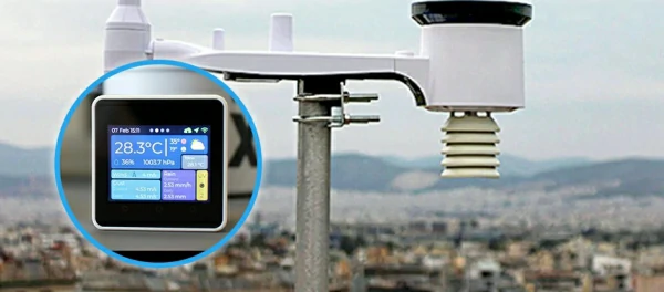


 Official Shop