Product

RS485 Communication in IoT: Bridging the Gap Between Devices

With the continuous development of the Internet of Things (IoT) technology, an increasing number of devices require remote monitoring and control. In this context, RS485 communication, as a reliable communication protocol, is widely used for data transmission and communication connectivity between IoT devices.

RS485 communication, as a serial communication protocol, offers several prominent advantages:

1. Long-distance transmission: RS485 communication supports transmission over a maximum distance of 1200 meters, suitable for communication needs among IoT devices distributed over larger areas.
2. Strong anti-interference capability: RS485 communication uses differential signal transmission, exhibiting excellent anti-interference capability, ensuring stable and reliable data transmission in industrial environments.
3. Multi-point communication: RS485 supports multi-point communication, enabling the connection of multiple devices to form a network, meeting the inter-device connectivity requirements in IoT.
4. High-speed transmission: RS485 supports data transmission speeds of up to 10Mbps, meeting the data transfer speed requirements of IoT devices.

Applications of RS485 in IoT:

1. Industrial Automation:

In the field of industrial automation, RS485 communication is widely used for data transmission and control connectivity among various devices such as sensors, actuators, and PLCs. Through RS485 communication, these devices can achieve remote monitoring and control, enhancing production efficiency and work safety.

2. Smart Buildings:

In smart building systems, RS485 communication is used to connect various smart devices, such as lighting control systems, HVAC systems, and security systems, enabling data exchange and centralized management among devices. The stability and reliability of RS485 communication enable smart building systems to achieve efficient energy management and intelligent control.

3. Agricultural IoT:

In agricultural IoT applications, RS485 communication can be used to connect soil moisture sensors, weather stations, irrigation systems, and other devices, enabling remote monitoring of farmland environments and precision irrigation to improve crop yield and quality.

Future development of RS485 communication:

In conclusion, RS485 communication, as an important communication means in IoT, provides a reliable solution for data transmission and communication connectivity between different devices through its features such as long-distance transmission, strong anti-interference capability, and multi-point communication. As IoT continues to evolve, we have reason to believe that RS485 communication will continue to play an important role, building a solid bridge for interconnection among IoT devices.

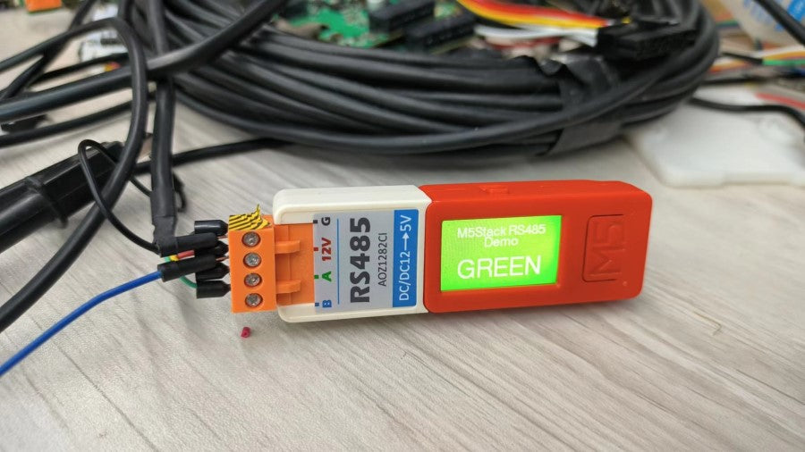
Next, we will use the M5Stack device as an example to demonstrate the application of RS485 communication in IoT. Here we use RS485 HAT, RS485 HAT consists of a 485 automatic transceiver circuit and a DC-DC buck circuit which can drop an input 12V to 5V.

Setting up the Arduino Environment

First, please refer to the Arduino IDE setup tutorial to complete the basic software installation. And then install the `M5Unified and FastLED libraries` in the library manager, or manually clone and install them from the following GitHub links into the C:\Users\PC\Documents\Arduino\libraries  directory:

*M5Unified: (https://github.com/m5stack/M5Unified)

*FastLED: (https://github.com/FastLED/FastLED)

Setting up the Hardware Environment

Devices needed:

1.  ATOM Matrix x1
2. M5StickC Plus x1
3. RS485 HAT x1
4. Tail485 x1
5.120 Ohm plug-in resistor x1
6. RS485 cable x1
7. 12V power supply x1

Operational steps:

1.Connect the RS485 HAT to the M5stickc Plus.

2. Connect the ATOM Matrix to the Tail485.

 3. Connect a 120-ohm matching resistor is needed at the AB end of RS485.

4. Use a 12V power supply.

5. Connect using the RS485 cable.

RS485 Transmitter

Using the following code, we will utilize the M5stickc Plus + RS485 HAT to create an RS485 transmitter. Pressing button A will send control commands via RS485 to control the color of the receiving end's RGB light.

#include "M5Unified.h"

String command[3] = {"RED\n", "GREEN\n", "BLUE\n"};

uint8_t command_index = 0;


void setup() {

  M5.begin();

  M5.Display.setEpdMode(epd_mode_t::epd_fastest);

  M5.Display.setFont(&fonts::Font4);

  M5.Display.setTextColor(WHITE);

  if (M5.Display.width() < M5.Display.height())

  { /// Landscape mode.

    M5.Display.setRotation(M5.Display.getRotation() ^ 1);

  }

  M5.Display.startWrite();

  M5.Display.setTextSize(1);

  M5.Display.drawCenterString("M5Stack RS485", M5.Display.width()/2, M5.Display.height()/8);

  M5.Display.drawCenterString("Demo", M5.Display.width()/2, M5.Display.height()/8+20);

  M5.Display.setTextSize(1);

  M5.Display.drawCenterString("btnA send command", M5.Display.width()/2, M5.Display.height()/8+60);

  M5.Display.endWrite();

  Serial2.begin(115200, SERIAL_8N1, 26, 0);

  while (1)

  {

    M5.update();

    M5.Display.startWrite();

    if (M5.BtnA.wasClicked()) {

      command_index++;

      if (command_index > 2)

        command_index = 0;

      Serial2.printf("%s", command[command_index].c_str());

      switch (command_index)

      {

      case 0:

        M5.Display.clear(RED);

        break;

      case 1:

        M5.Display.clear(GREEN);

        break;

      case 2:

        M5.Display.clear(BLUE);

        break;


      default:

        break;

      }


      M5.Display.setTextSize(1);

      M5.Display.drawCenterString("M5Stack RS485", M5.Display.width()/2, M5.Display.height()/8);

      M5.Display.drawCenterString("Demo", M5.Display.width()/2, M5.Display.height()/8+20);

      M5.Display.setTextSize(2);

      M5.Display.drawCenterString(command[command_index], M5.Display.width()/2, M5.Display.height()/8+60);

      M5.Display.endWrite();

      break;      

    }

  }

}


void loop() {

  M5.update();

  M5.Display.startWrite();

  if (M5.BtnA.wasClicked()) {

    command_index++;

    if (command_index > 2)

      command_index = 0;

    Serial2.printf("%s", command[command_index].c_str());

    switch (command_index)

    {

    case 0:

      M5.Display.clear(RED);

      break;

    case 1:

      M5.Display.clear(GREEN);

      break;

    case 2:

      M5.Display.clear(BLUE);

      break;


    default:

      break;

    }

  }


  M5.Display.setTextSize(1);

  M5.Display.drawCenterString("M5Stack RS485", M5.Display.width()/2, M5.Display.height()/8);

  M5.Display.drawCenterString("Demo", M5.Display.width()/2, M5.Display.height()/8+20);

  M5.Display.setTextSize(2);

  M5.Display.drawCenterString(command[command_index], M5.Display.width()/2, M5.Display.height()/8+60);

  M5.Display.endWrite();  

}

RS485 Receiver

With the code below, we utilize the ATOM Matrix+Tail485 to create an RS485 receiver. The receiver waits for commands sent by the transmitter and changes the color of the RGB LED.

#include "Arduino.h"

#include <FastLED.h>


#define NUM_LEDS 25


#define DATA_PIN 27


CRGB leds[NUM_LEDS];


char terminateChar =  '\n';      

const int bufferLength = 100;    

char serialBuffer[bufferLength];

String rx_str;  


void setup() {

    FastLED.addLeds<NEOPIXEL, DATA_PIN>(leds, NUM_LEDS);


    Serial2.begin(115200, SERIAL_8N1, 32, 26);

}


void loop() {

    if (Serial2.available()) {

        Serial2.readBytesUntil(terminateChar, serialBuffer, bufferLength);

        rx_str = serialBuffer;

        if (rx_str.indexOf("GREEN") != -1) {

            for (int i = 0; i < 25; i++)

                leds[i] = 0x001000;

            FastLED.show();

        }

        else if (rx_str.indexOf("RED") != -1) {

            for (int i = 0; i < 25; i++)

                leds[i] = 0x100000;

            FastLED.show();

        }

        else if (rx_str.indexOf("BLUE") != -1) {

            for (int i = 0; i < 25; i++)

                leds[i] = 0x000010;

            FastLED.show();

        }

    }

}

0 comments

  • There are no comments yet. Be the first one to post a comment on this article!

Leave a comment

Please note, comments must be approved before they are published

Liquid error (layout/theme line 209): Could not find asset snippets/pe-disco-countdown-timer.liquid